
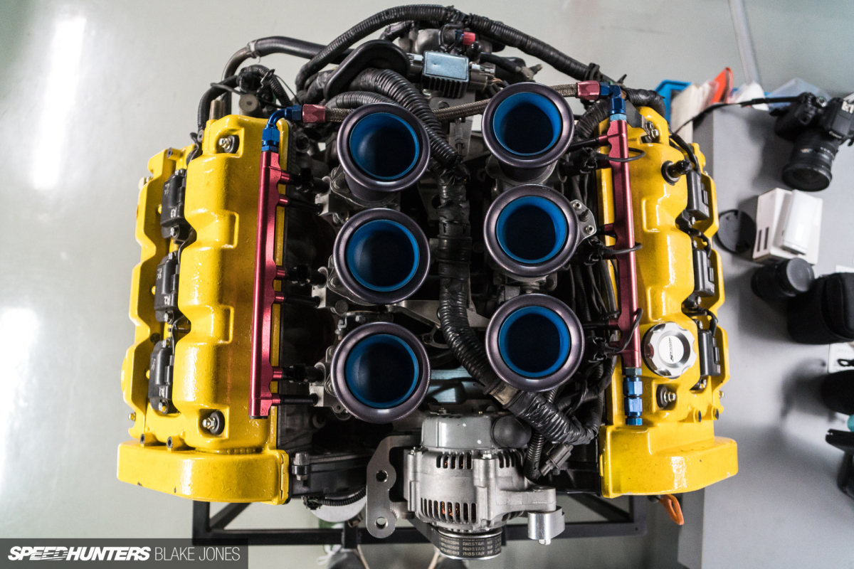
What do we love so much about naturally aspirated engines? Perhaps the musicality, or the responsiveness, or the combination of both that creates an emotionally rewarding experience with every stab at the throttle pedal. Well, whatever underpins that appeal, I can say for sure that nothing turns it up to 11 quite like a set of individual throttle bodies.
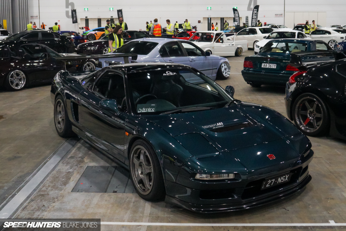
Enter Project NSX. Already providing a symphony of surround sound from the mid-mounted engine and making almost enough power to satisfy – the scene was set. ITBs. More power. More sound. Less weight. More… mechanical sex appeal. I want it. Nay, I need it!
For those long-term followers of the project – thank you for your patience – you might remember the ‘Stage 2′ target of 300 crank horsepower outlined all the way back in 2019. Six years ago, really? Yes, and it’s time to finally tick that box.
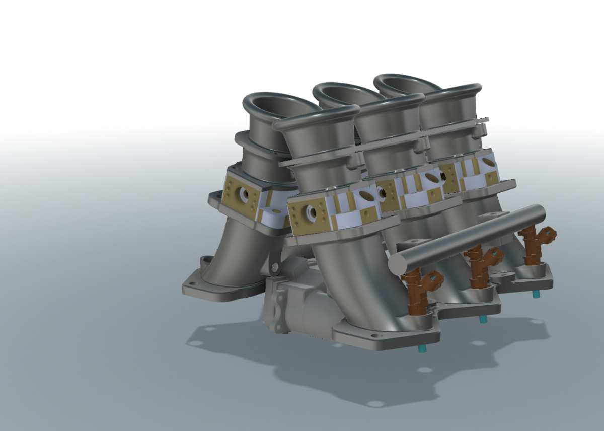
Before deciding to go the ITB route, I was already aware of a few kits available for the NSX’S C30A 3.0L DOHC VTEC V6 engine. As with many aftermarket offerings for the NSX, they are mostly expensive and compromised. I wanted to run drive-by-wire, and nothing was particularly suited to that. Injector position was a particularly weak point, with most available solutions placing them at angles perpendicular to the airflow, acceptable for high-RPM operation in a race car but eliminating the benefit of proper spray targeting at lower intake air speeds. Compromising the NSX’s famous low-speed manners in this way was unacceptable, so I started to play around with a bespoke solution. I had some CAD experience from my 3D printing escapades, how hard could it be?
I soon found out – rather difficult indeed. The complex shapes required to match the angle and profile of the intake ports were a particular challenge, countless late nights were spent with Fusion360 and YouTube open, learning on the job. Making mistakes, throwing it all in the bin, and starting again. By the time I had something ready for prototype production, I think I was on to version 18… a prime example of biting off more than you can chew, but that’s also the best way to accelerate your learning.
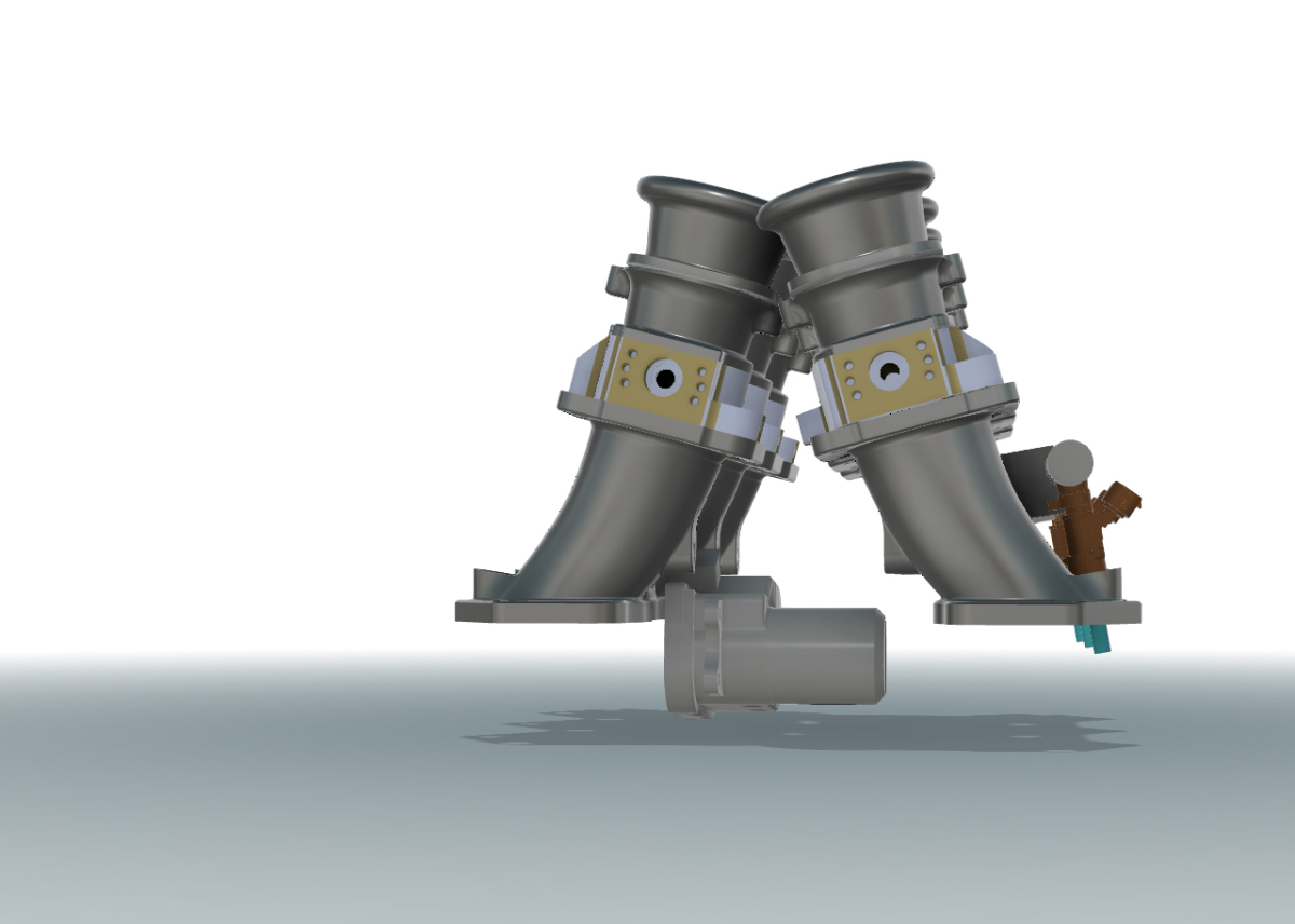
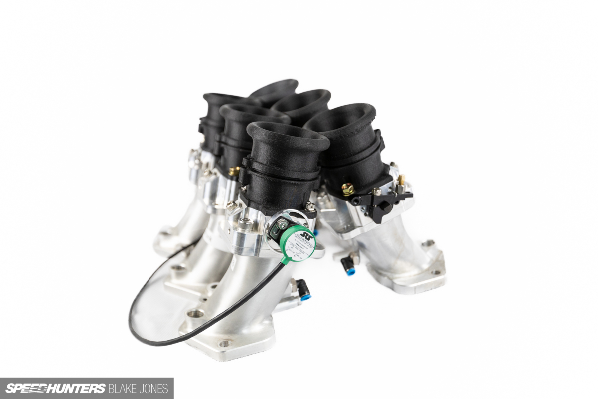
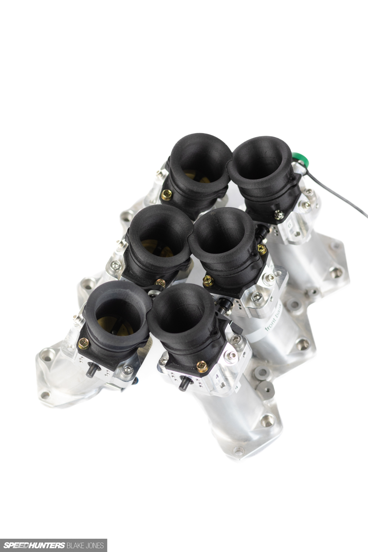
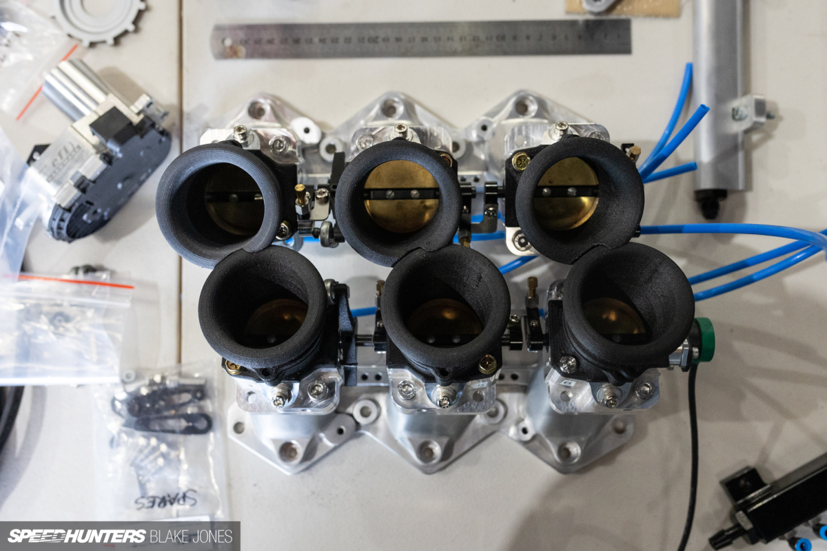
The key features – a runner profile 3D matched to the shape and direction of the intake ports and a 48mm throttle body, injector position identical to factory, including angled mounting position, provision for the mounting of a central DBW throttle actuator, and angled runners to clear the alternator and mount. It was at this stage I also selected some other key components from some great Australian suppliers, namely six 48mm throttle bodies and associated linkages from RHD Engineering, and a DBW throttle actuator from EFI Hardware. The mounting points on my manifold design were positioned to match.
Design To Manufacture
After a few printed plastic iterations, it was ready for the real thing. I had at one stage considered printing the final product in a strong and heat-resistant carbon-filled nylon but was eventually steered away from that by those who know better – the risk of the manifold flexing/warping due to heat/load and thus misaligning the throttles was substantial. Instead, I’d opt for CNC-machined 6061 aluminium.
I shopped around for some quotes locally and overseas, eventually settling on a manufacturer based in China. There were a few minor bumps through the process, but I cannot fault the company on its communication or responsiveness. I was sent photos at every stage of the manufacture and QC process and would happily go this route again.
The cost of this machining was substantial, much higher than I’d anticipated. The complexity of the part (and thus the machining effort and time required) was the culprit – and another lesson learned: designing with the production method in mind is important. Additive manufacturing had spoiled me – no tool paths to consider on the printer.
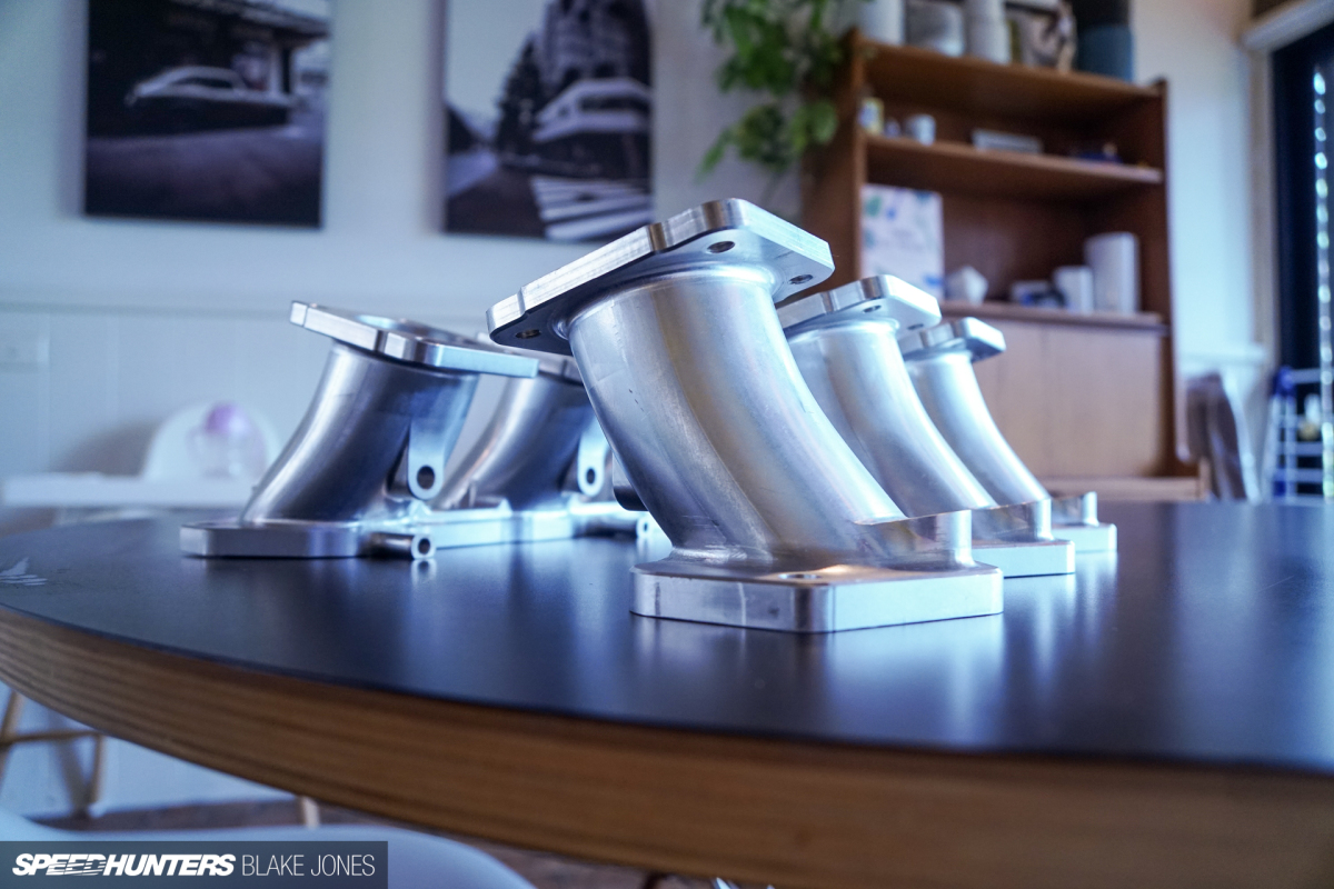
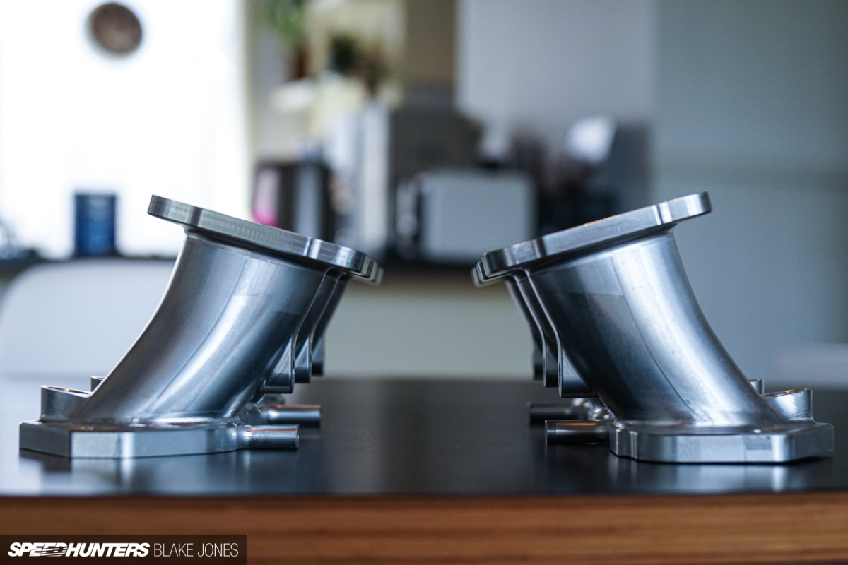
But having the design in my hand in billet aluminium after a few short weeks was a huge thrill, and after months of tweaking in CAD, it finally meant I could move towards assembly of the full system.
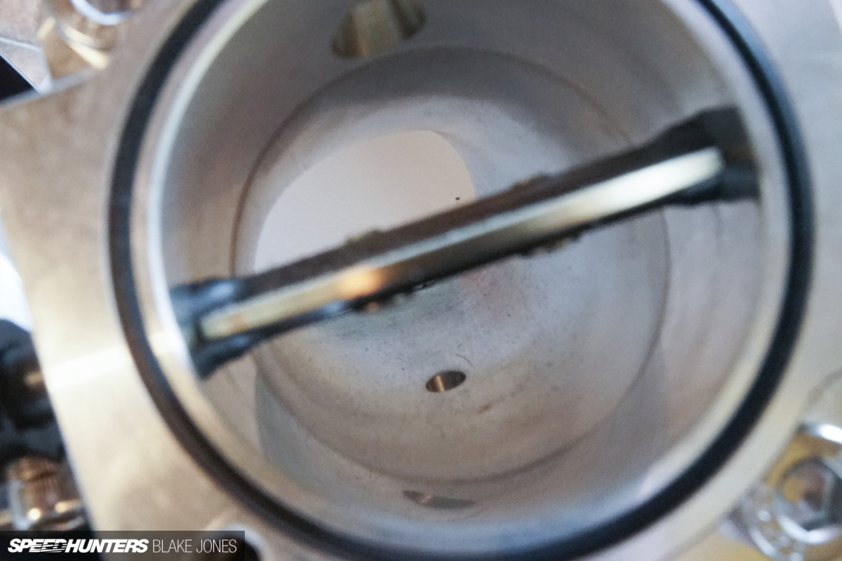
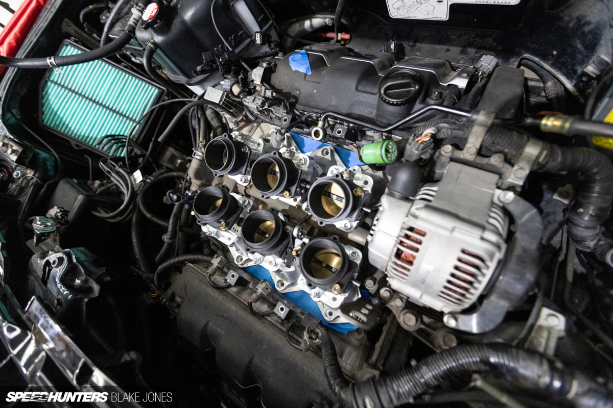
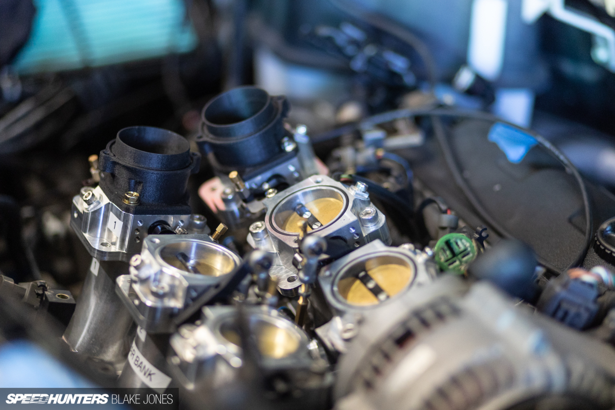
Connecting seamlessly to the top of each runner is an RHD Engineering 48mm throttle body.
Throttle sizing is a key decision to be made early on when designing a multi-throttle system. Too big and you may lose throttle resolution and, depending on the shape of the overall runner, air velocity. Too small and you will restrict the maximum airflow at wide open throttle. Although the calculated ‘optimum’ throttle size was quite small, referencing a collection of other NSX ITB implementations as well as OE designs from the likes of Porsche and BMW suggested that the 48mm ballpark would support my target power output for this fairly standard engine, and allow margin for the impact of boundary layer effects, throttle plate restrictions etc., and some headroom for future power goals. The NSX has quite large ports from factory, so going any smaller than 48mm would also create a ‘choked’ runner profile which would negatively impact velocity and cylinder filling. The existing options for the NSX start at 48mm and extend right up to a whopping 60mm, perhaps optimised for engines with larger capacities and higher RPM capabilities.
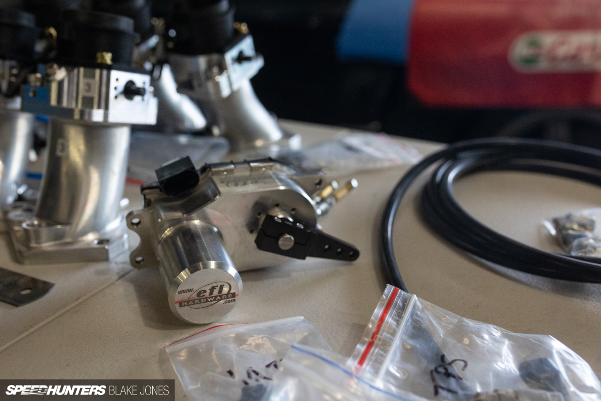
I’d previously adapted the car to run a (single) drive-by-wire throttle body and was enjoying the benefits of adjustable throttle response and engine safety strategies. The EFI Hardware motor uses the same principles of an electronic throttle body, but actuates an adjustable lever which makes it adaptable to multi-throttle systems.
Some 3D-printed airbox mounts and bellmouths helped with mocking up the intake before final assembly.
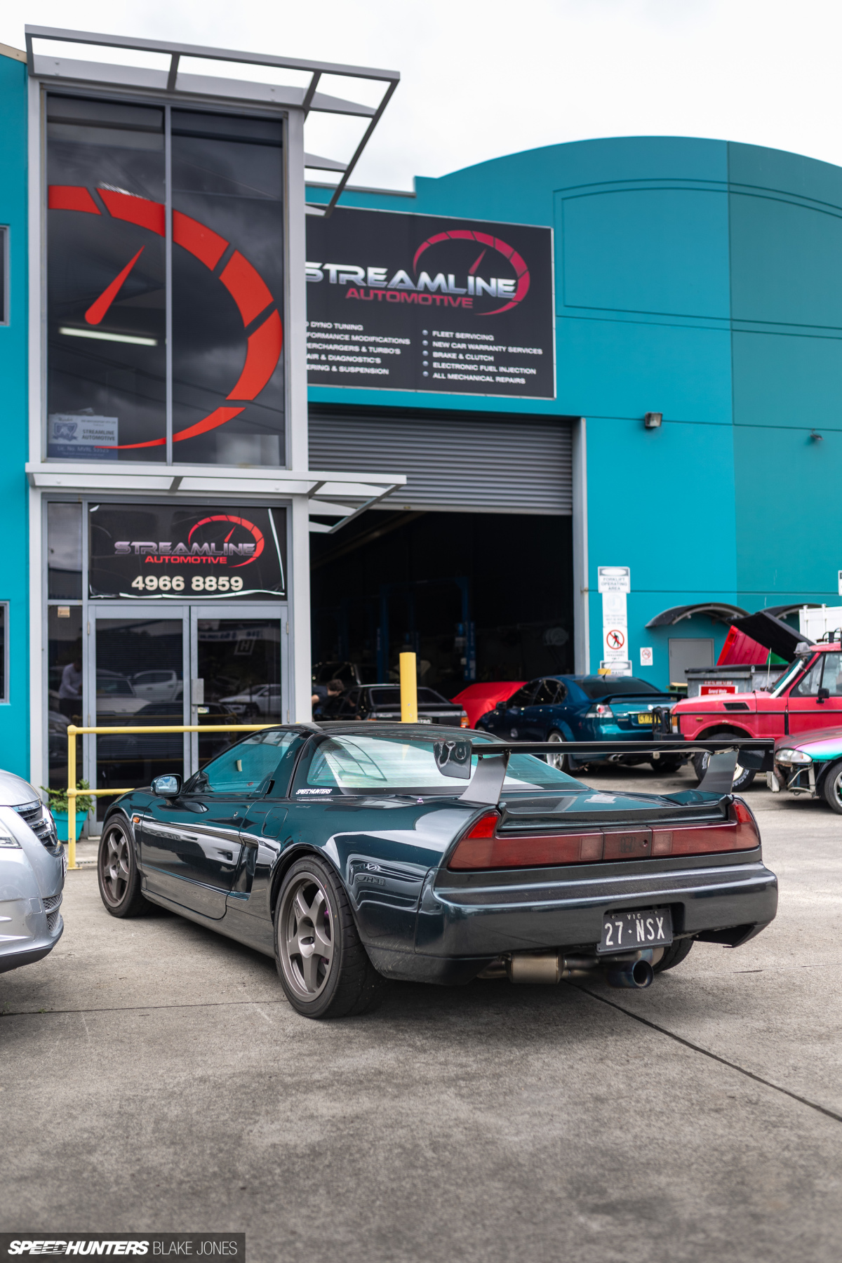
Once I’d assembled most of the components to put the kit together, it was time to make the long journey from Melbourne to Newcastle, home of 909 Motorsport. My day job at Bosch Motorsport has introduced me to some exceptional motorsport minds, including Ash and his team at 909. They were the trusted hands required to finesse this ITB project to completion.
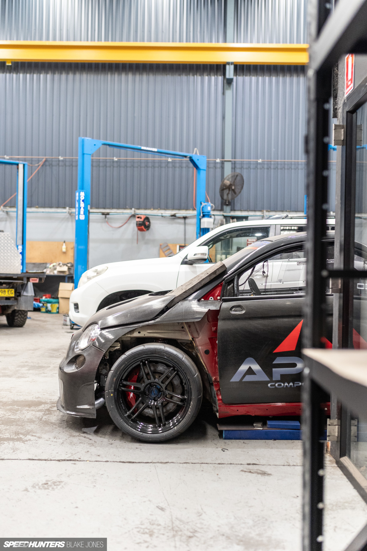
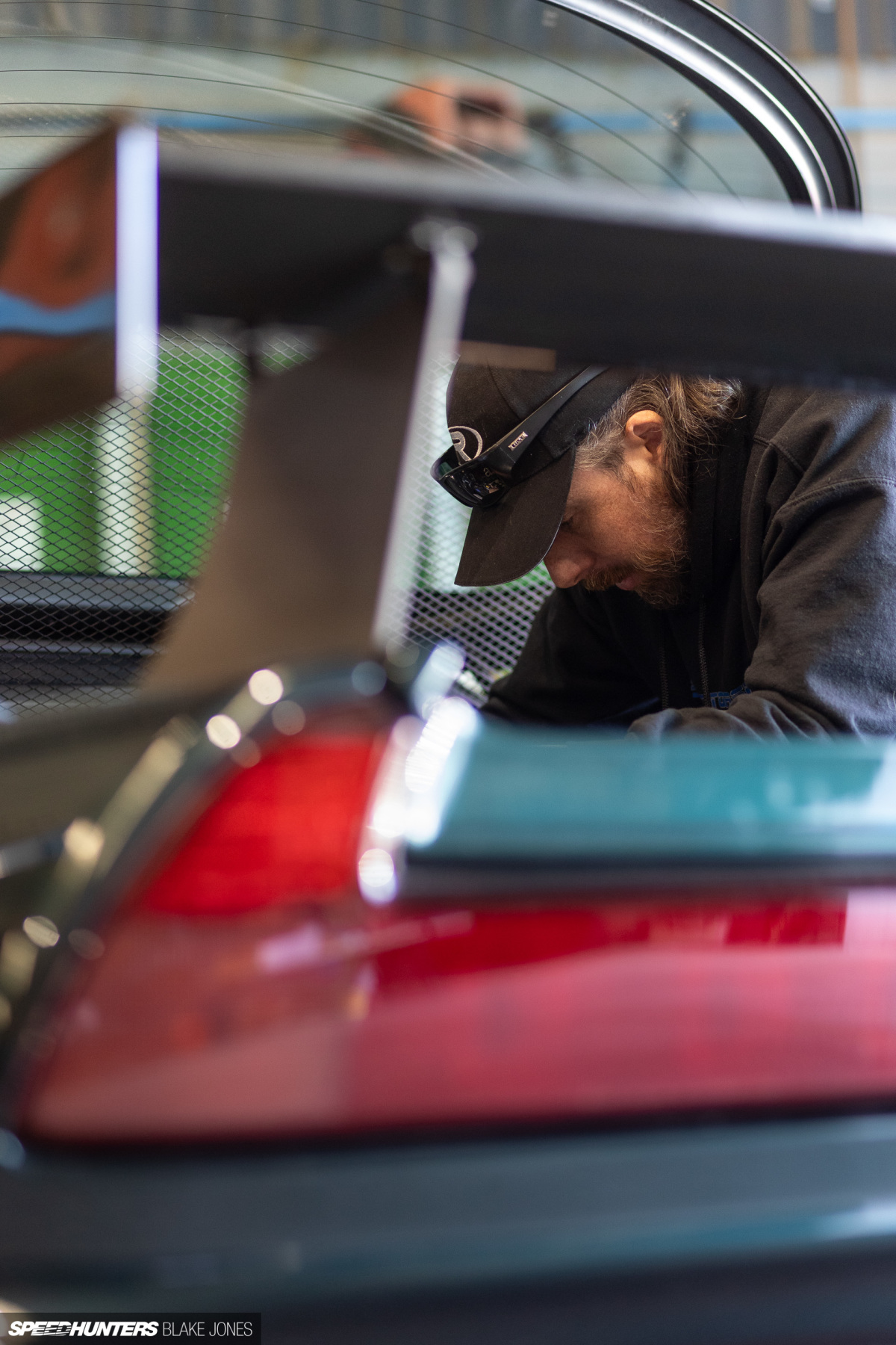
The regular vehicle servicing that happens at the front of the shop belies the magic that happens at the back, where a couple of lifts are reserved for motorsport projects. Ash’s passion for oddball European machinery means there is always an interesting customer car to stick your head into…
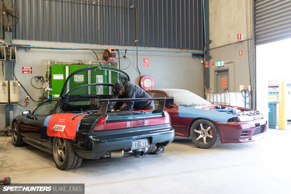
While Ash stuck his head into making the ITB magic happen.
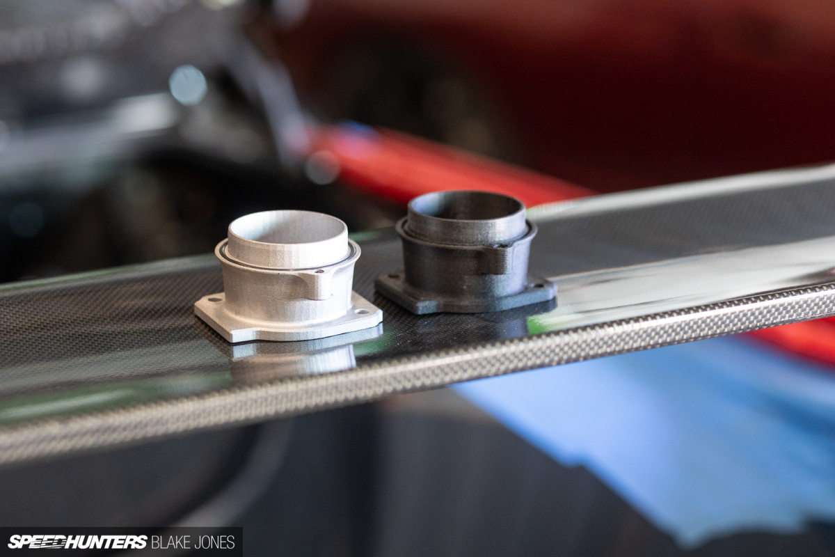
I decided the spacers which connect the throttle body to the airbox base were perfect for an experiment in metal 3D printing, electing to have them made out of aluminium. Being my first outsourced metal print I was excited and curious to see the quality of the part.
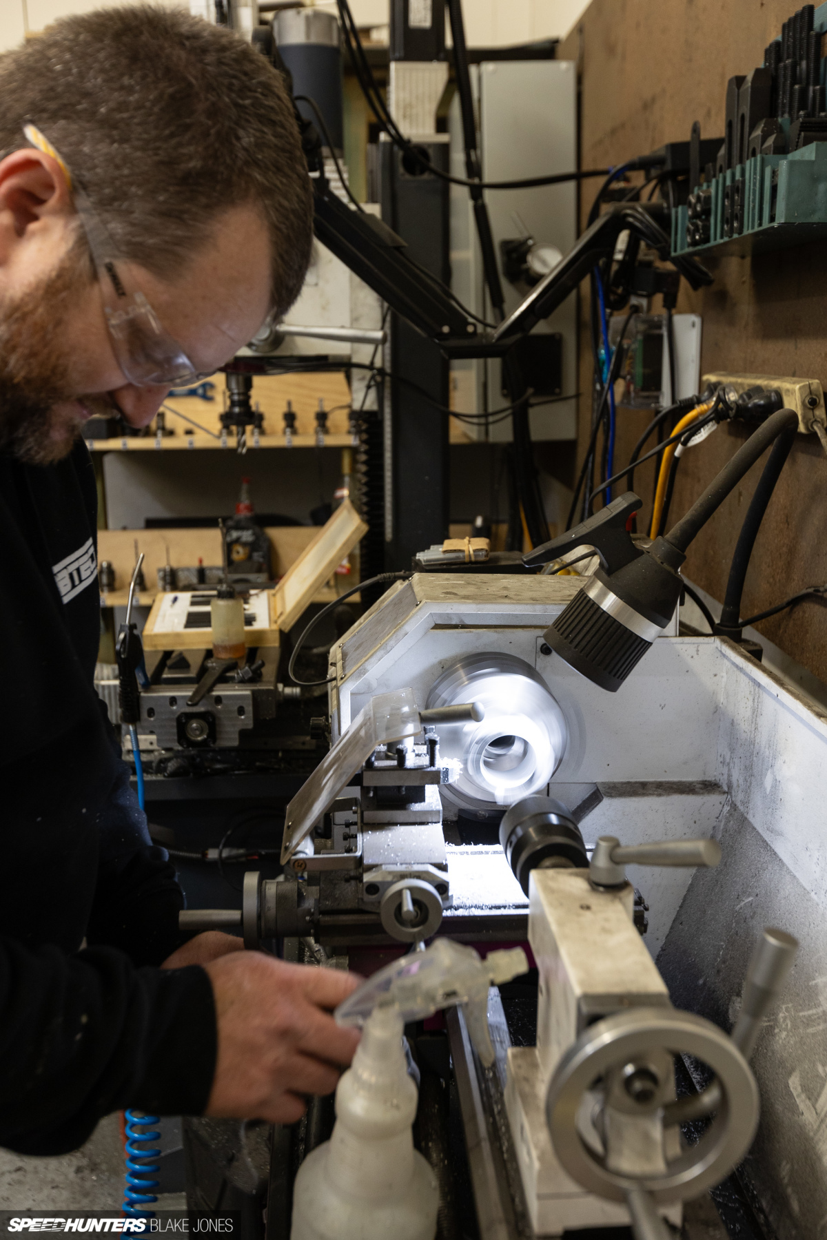
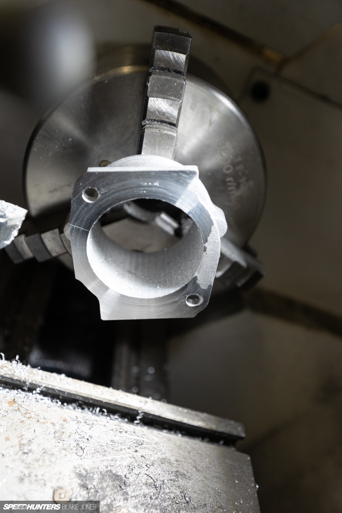
Overall I was very impressed with what arrived from the printer, with the bottom mounting surface being the only area that benefited from a resurfacing on the lathe at the skilled hand of Eric of Apex Composites to get it completely flat.
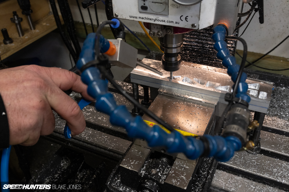
Eric is one of those rare individuals who can always see a path to achieve the objective. A potent mix of creativity and technical proficiency which I am equal parts envious and in awe of.
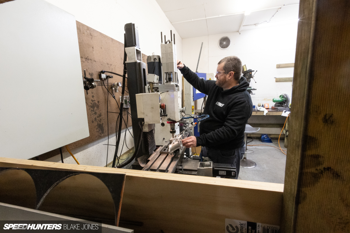
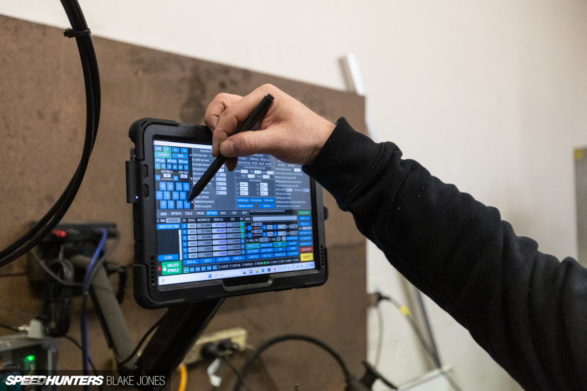
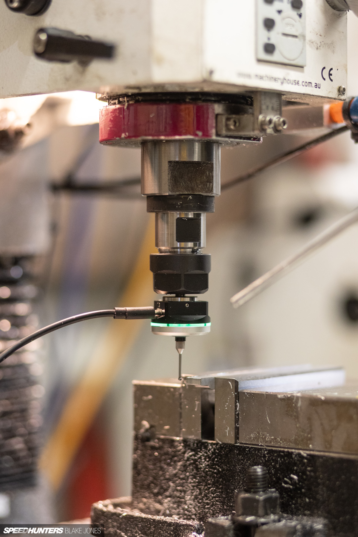
In several instances where I had seemingly designed myself into a difficult corner, Eric fired up the (home-made) CNC and machined an elegant solution.
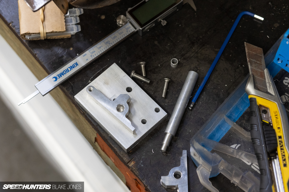
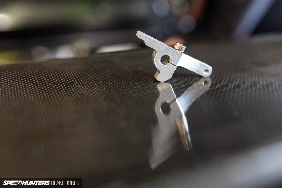
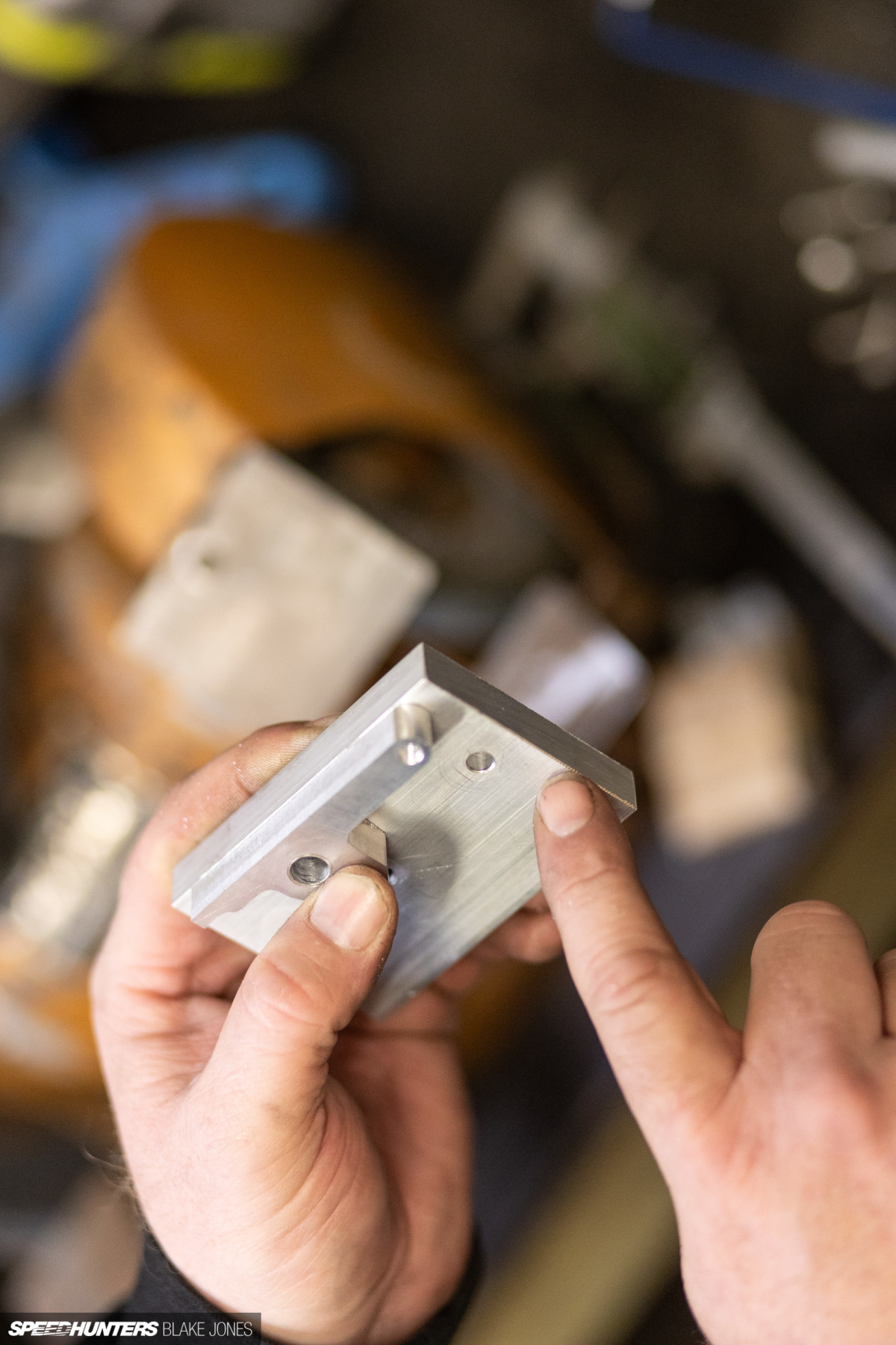
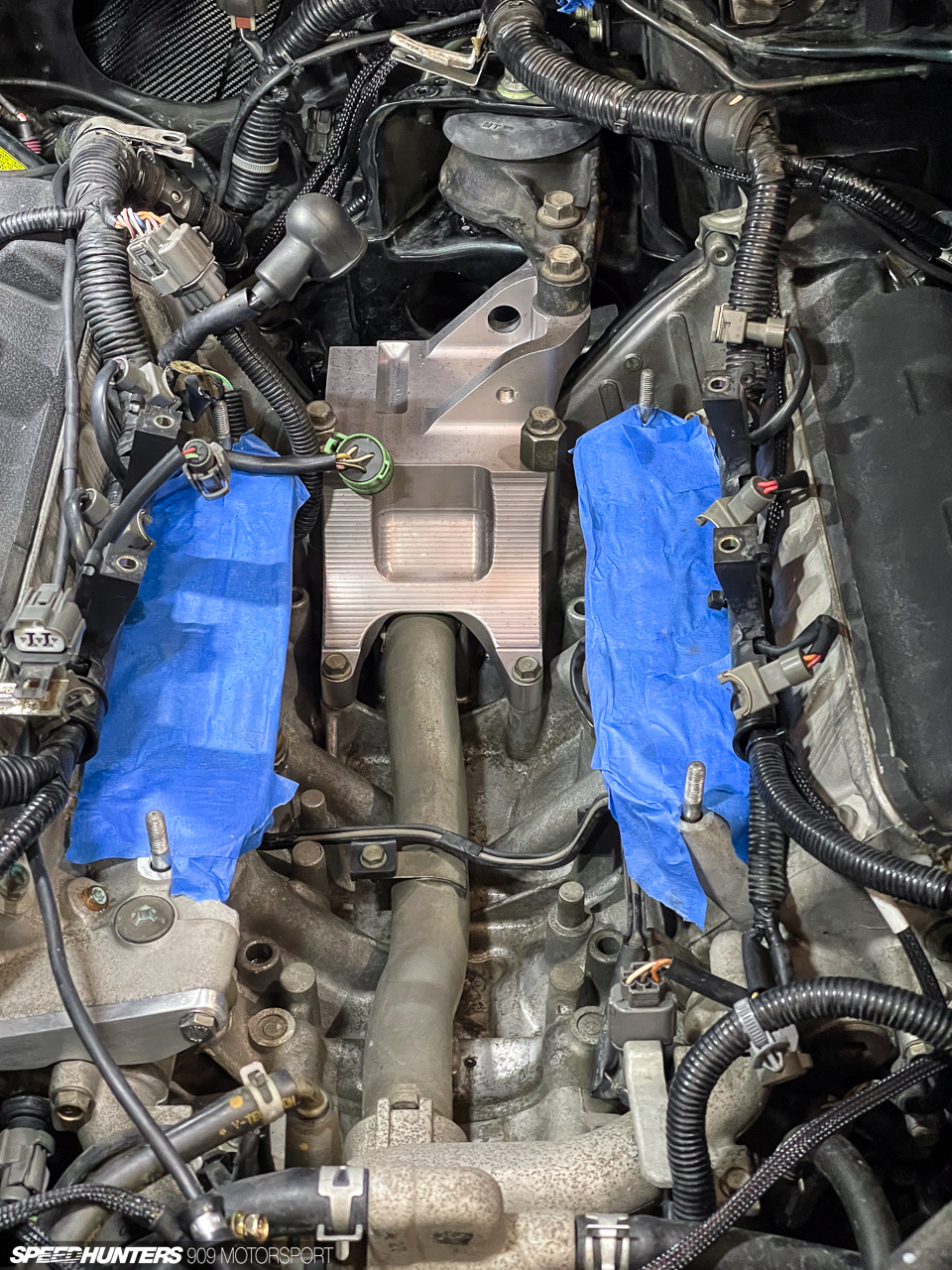
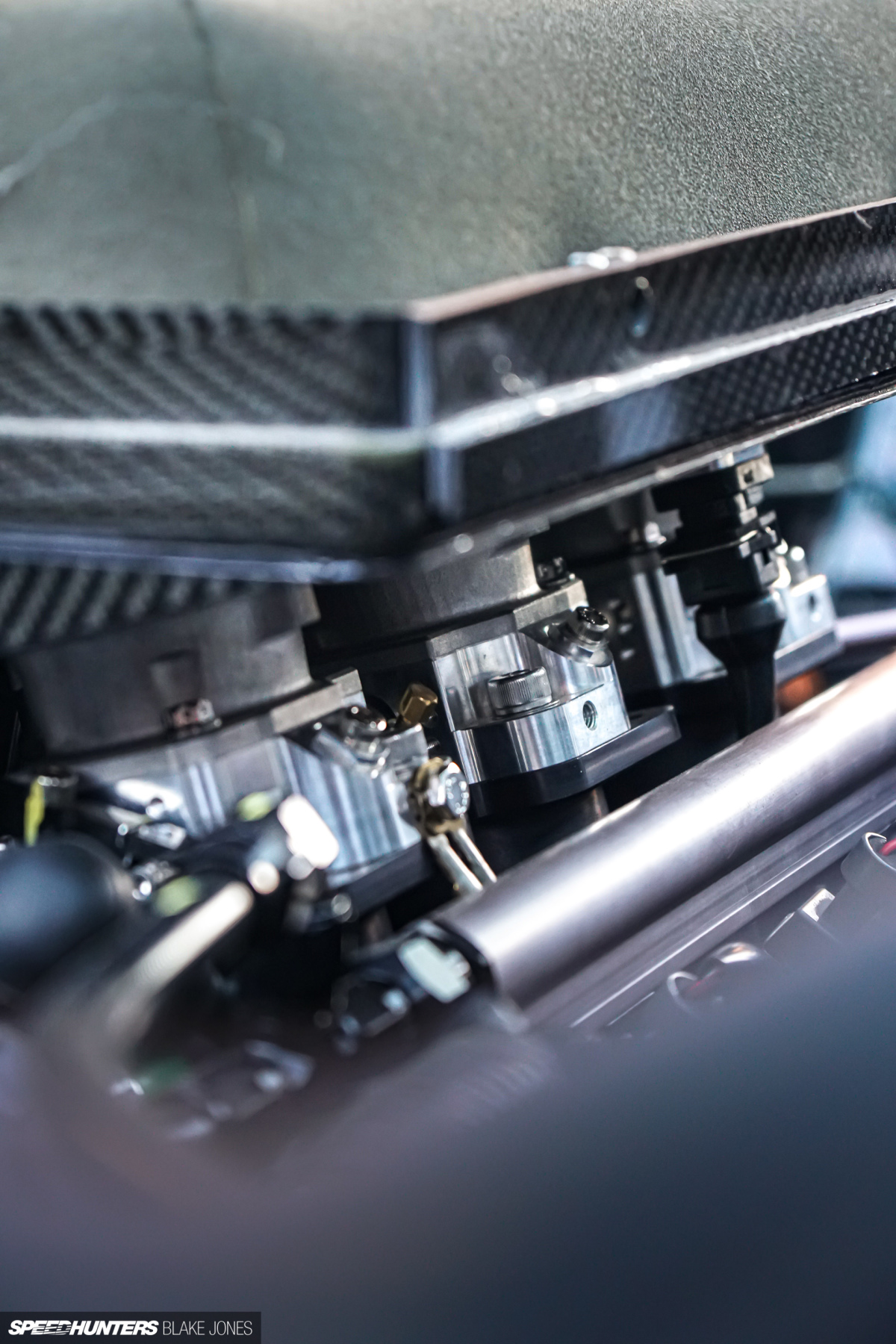
This included some extended-length throttle linkage arms which enabled a central pull of the two throttle banks from the throttle motor mounted in the central vee of the engine.
Also, a beautiful bracket (pocketed to save weight) to mount the vacuum manifold and accessories between the two banks.
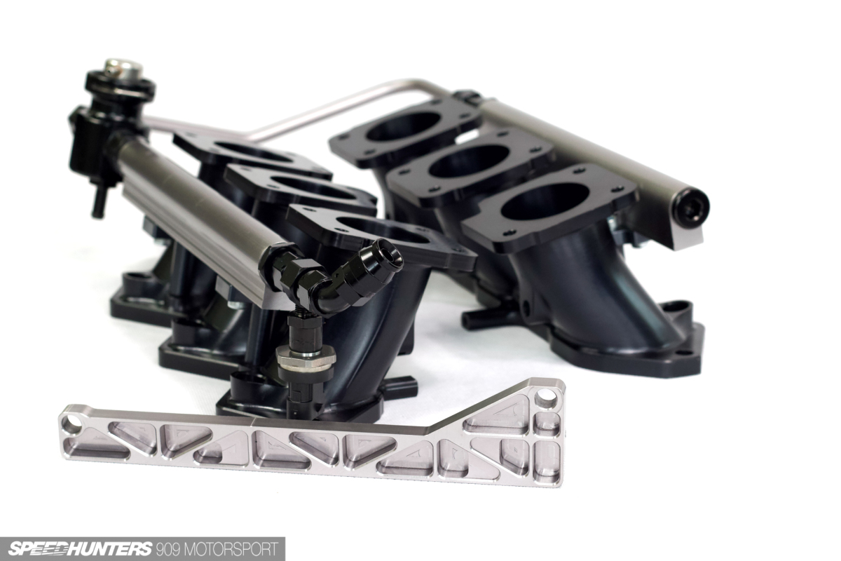
Once the fabrication of the various aluminium components was completed, Eric also treated them to an anodisation to improve the durability and corrosion resistance – not to mention the aesthetics. I was pretty giddy seeing the parts like this for the first time.
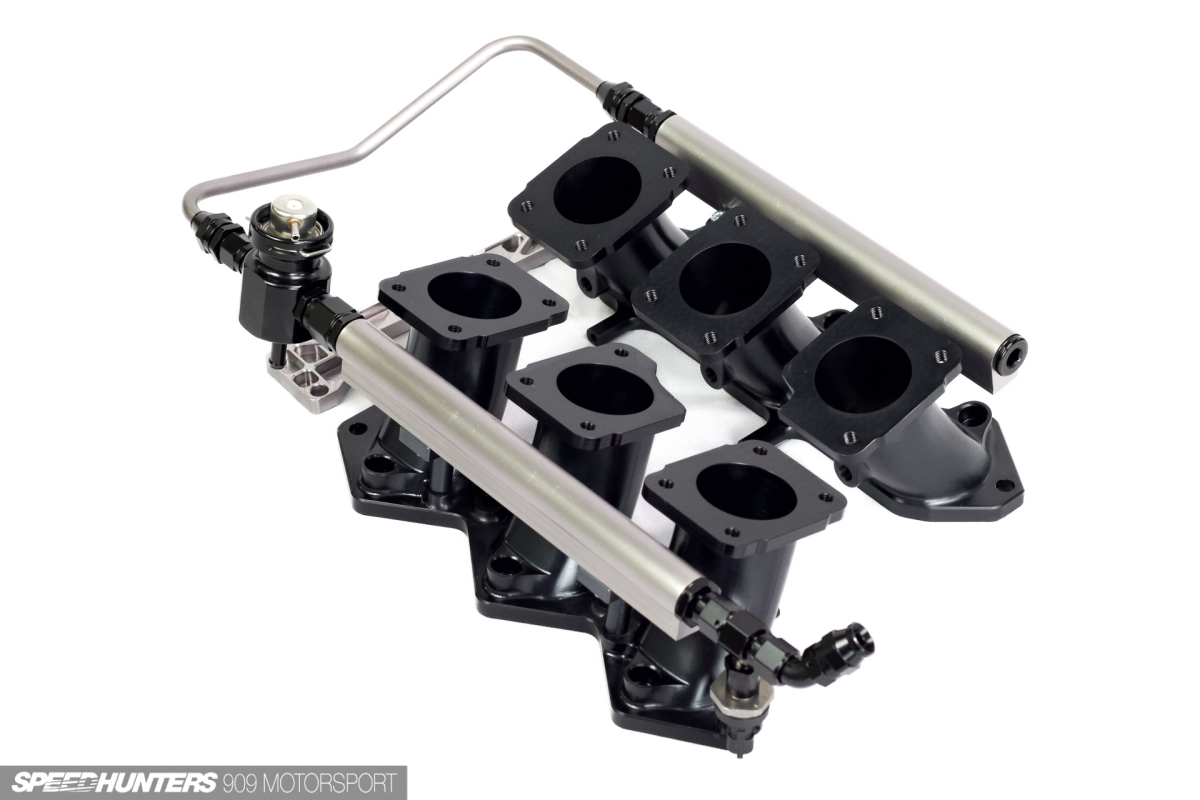
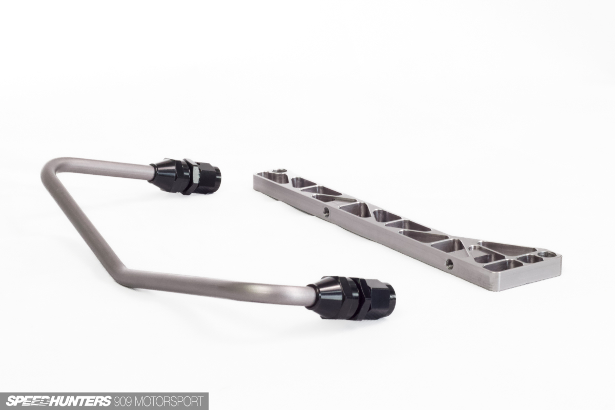
Custom fuel rails with hard lines bent to precisely match the vee of the intake – does it get any better? Touches like this I never would have been able to execute without the involvement of Ash and Eric, and for that I am extremely grateful.
The process of actually mounting the manifold was extended, with lots of test fitting, adjusting, and aforementioned fabrication. Through this process I was reminded of the difference between designing parts like this and actually engineering them to work with the required level of performance and durability, and the importance of having experts in your corner.
One of the key decisions that Ash and Eric drove was to grub-screw every point of adjustment in the system once it was perfectly set up. This is a significant machining effort that requires skill and patience, which Eric (perhaps obvious to the readers at this point) has in buckets. A common complaint about multi throttle linkages is that they come out of alignment with time, requiring constant fiddling – not a problem anymore.
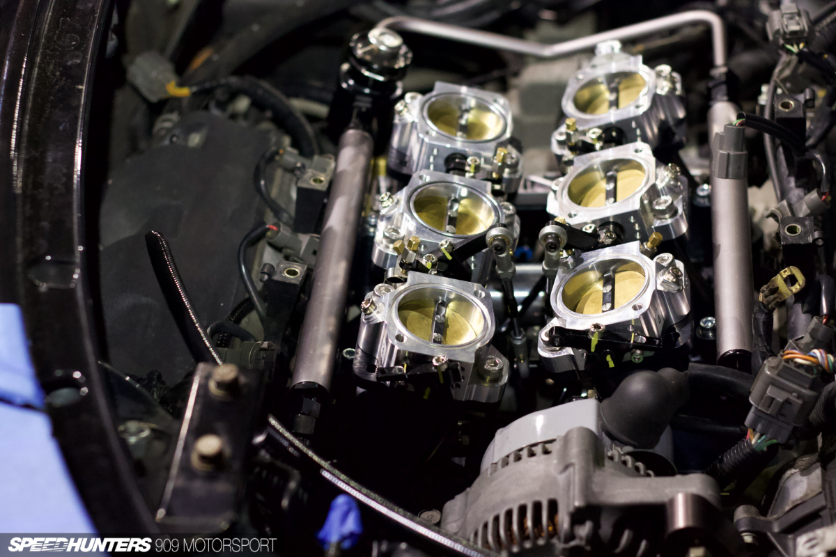
Mocked up on the car, I was finally starting to see the reality of the dream materialise. We were still miles away from the car running, but Ash knew what we needed for motivation – he quickly hooked up the throttle motor and sent it the command – open! Seeing the six throttles dance in unison was honestly a bit of an emotional moment – after hundreds of combined hours of planning and tinkering this madness actually might work.
Manufacture To Assembly
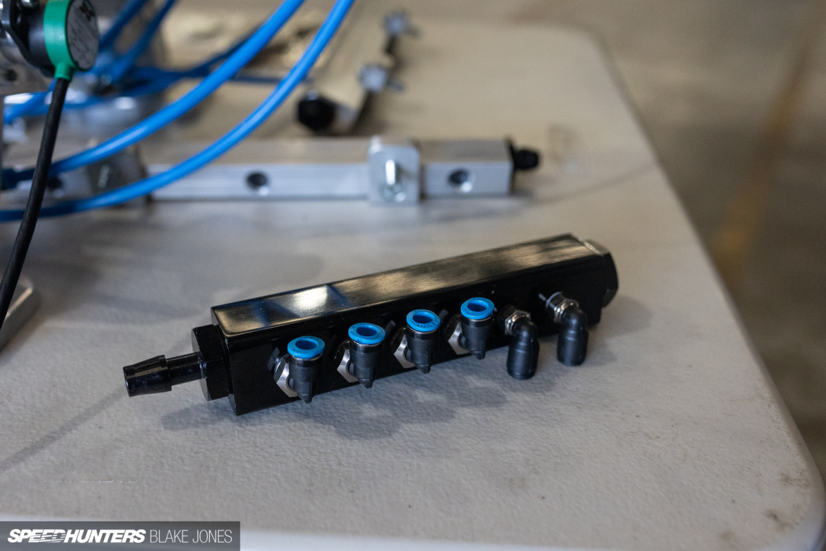
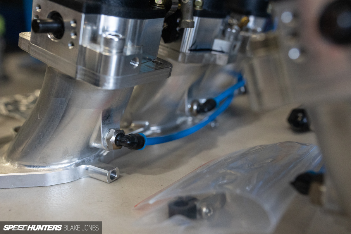
One of the main compromises of a multi-throttle setup is the loss of manifold volume downstream of the throttles. On a typical single-throttle setup, the manifold usefully holds a balanced source of vacuum from all cylinders, which provides a MAP (manifold air pressure) signal and consistent vacuum to feed brake booster, fuel pressure regulator reference, etc. The typical solution is to link the cylinders below the throttles to a smaller manifold, which is exactly what I did, using nylon Festo tube and high quality fittings to feed a cheap eight-port manifold.
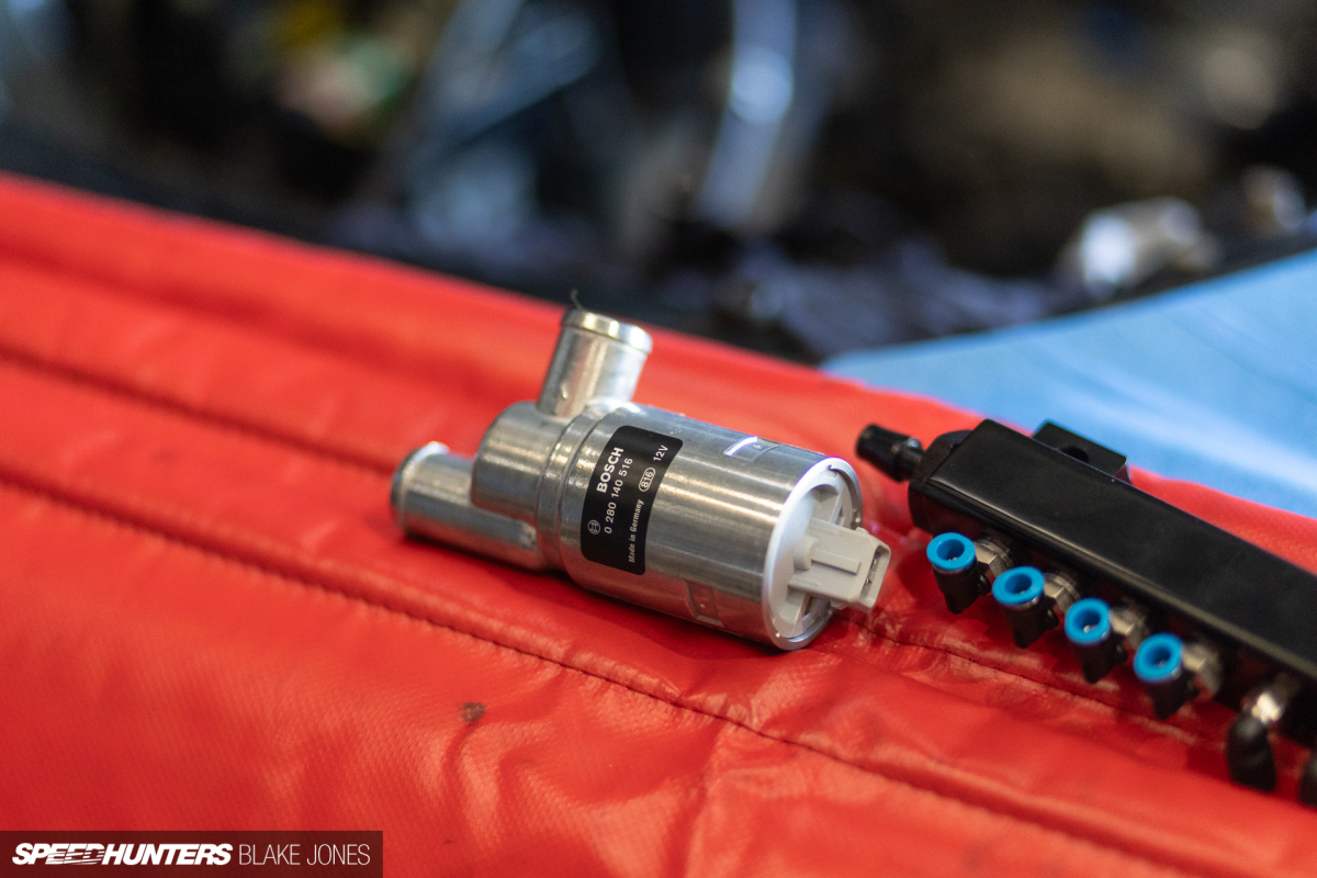
This is also where I integrated an electric idle valve. The drive-by-wire could, in theory, control the idle, however Ash’s experience showed that the resolution required for the precise idle control that would enable the uncompromised drivability would not be possible with that central motor alone.
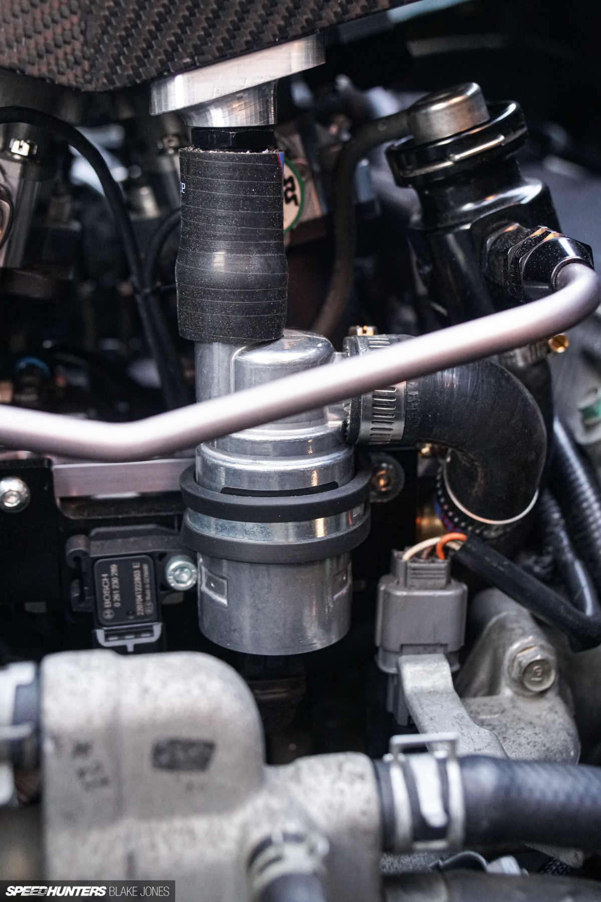
The reason for this is the extremely non-linear relationship between throttle position and airflow as a throttle cracks open – multiply this by six openings and the large inrush of air at even 1% throttle becomes impossible to manage to the high standard we were pursuing. A simple two-wire Bosch idle motor was an easy solution, integrated to take air from the filtered air box – with the most elegant machined aluminium adapter made by Eric.
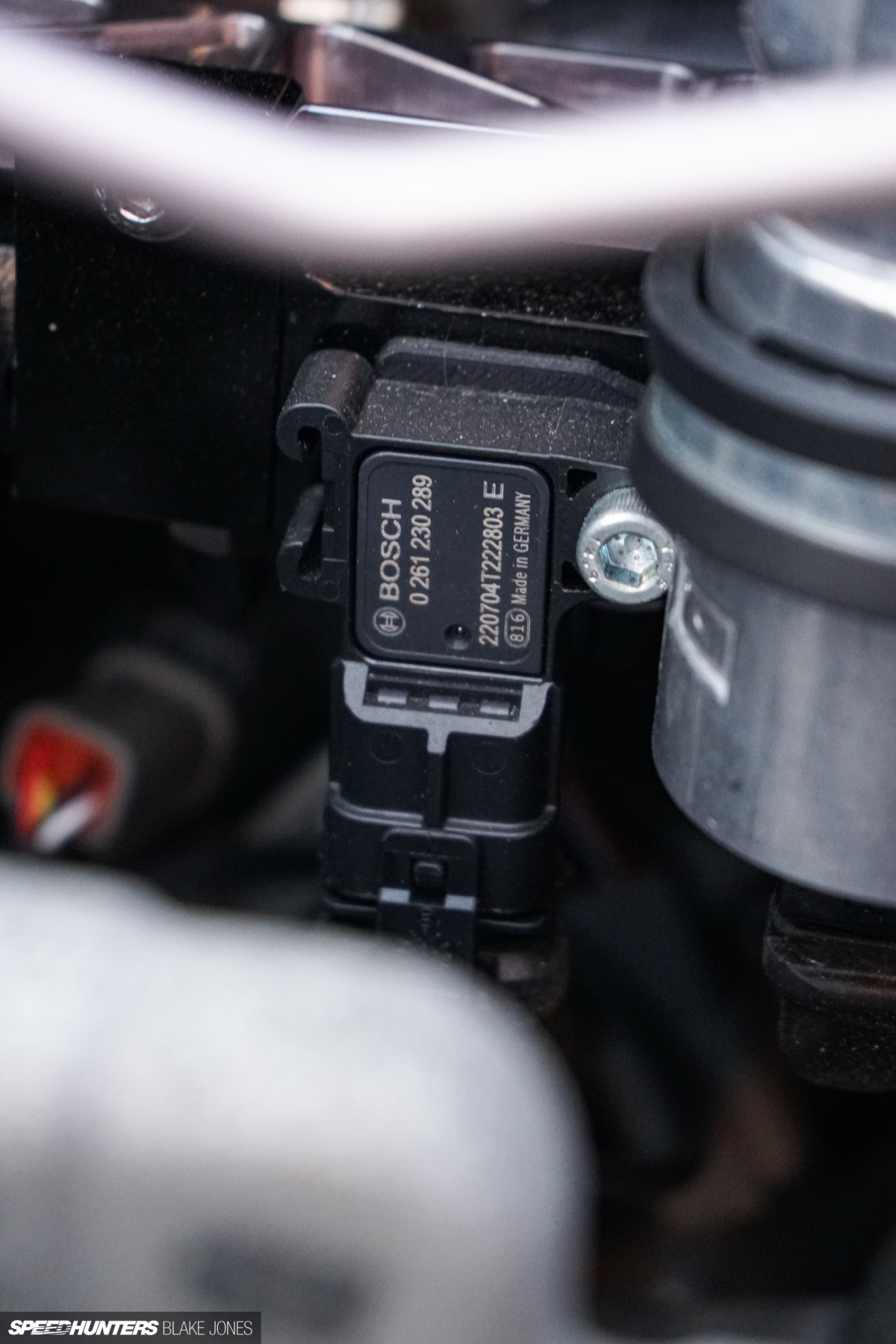
Into the same aluminium vacuum block was where we installed one of two air pressure (MAP) sensors. A Bosch Motorsport fast response air temp sensor neatly integrates into the air box with another piece of Eric’s functional jewellery.
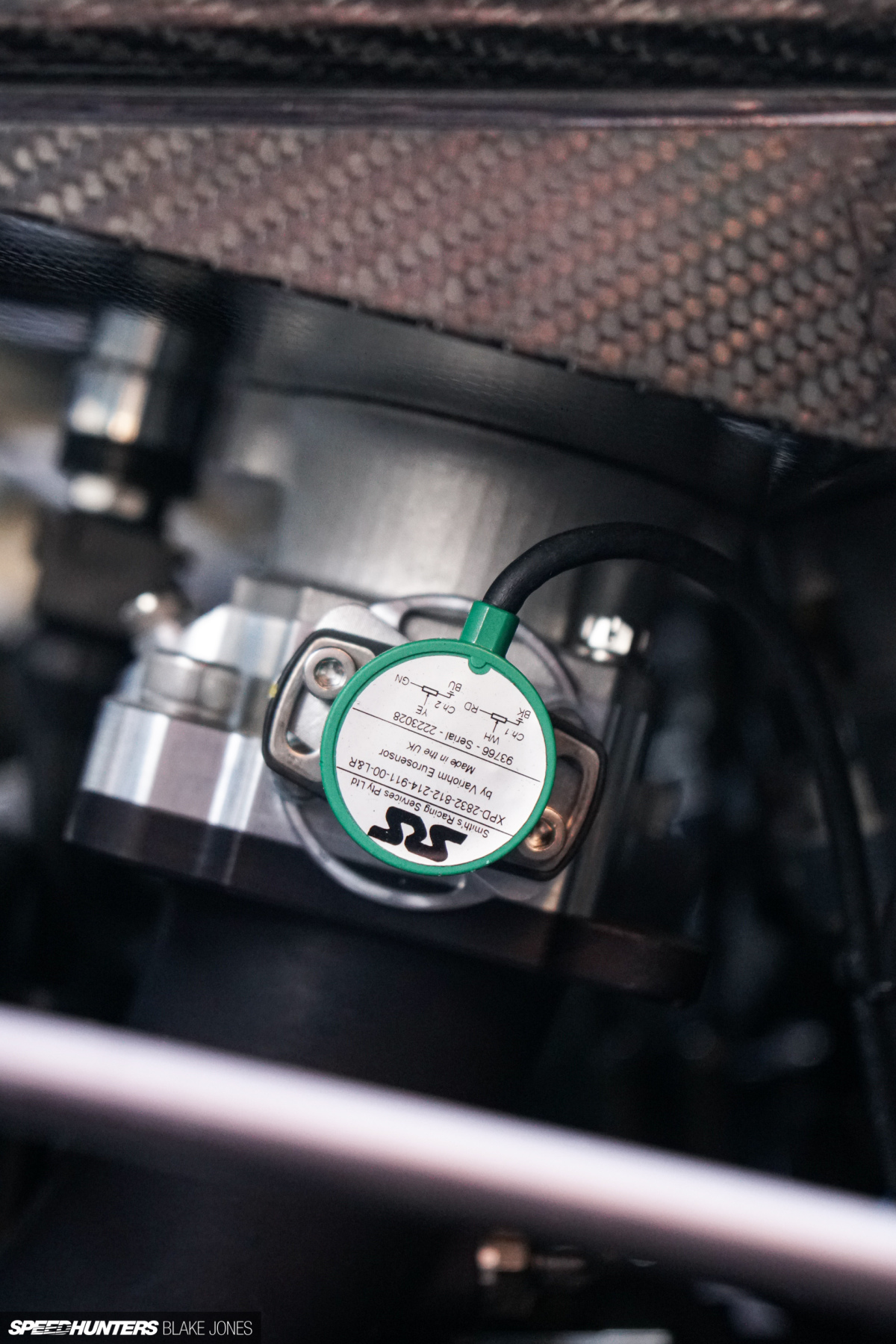
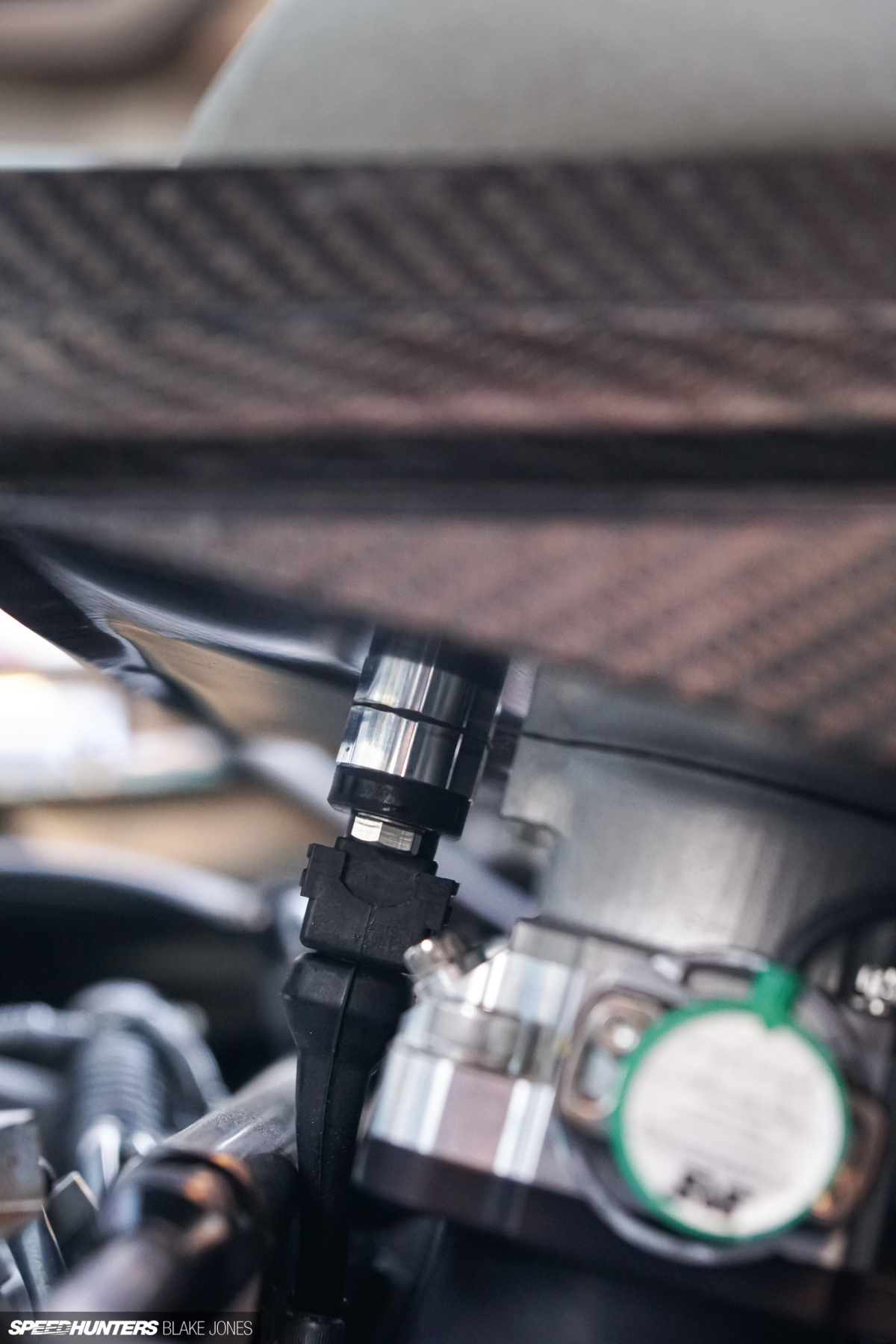
We have elected to not use the internal throttle position sensor in the throttle motor, instead using a Variohm TPS on each bank of the intake to generate a throttle position signal. This might seem like unnecessary complexity but is exactly the kind of decision that Ash will push you make despite it meaning more time and effort in the setup. Fundamentally, you want the ECU to know the position of the throttle blades, not the position of the motor driving them. In a multi-throttle system with a combination of various connections, linkages and joints, any slack in the system (and there is always some) becomes noise in the signal. Using the Alpha-N plus MAP load tuning method as we are here has TPS as a key input, so accuracy is of utmost importance.
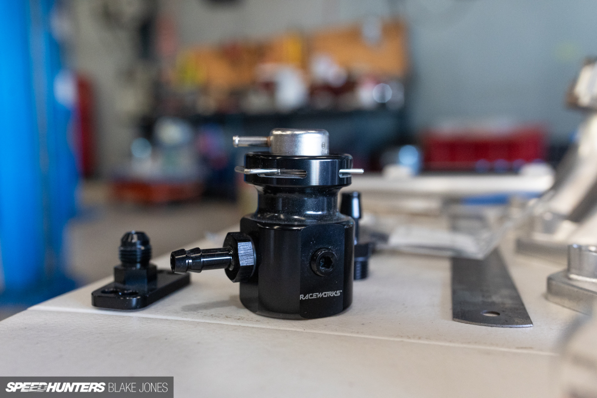
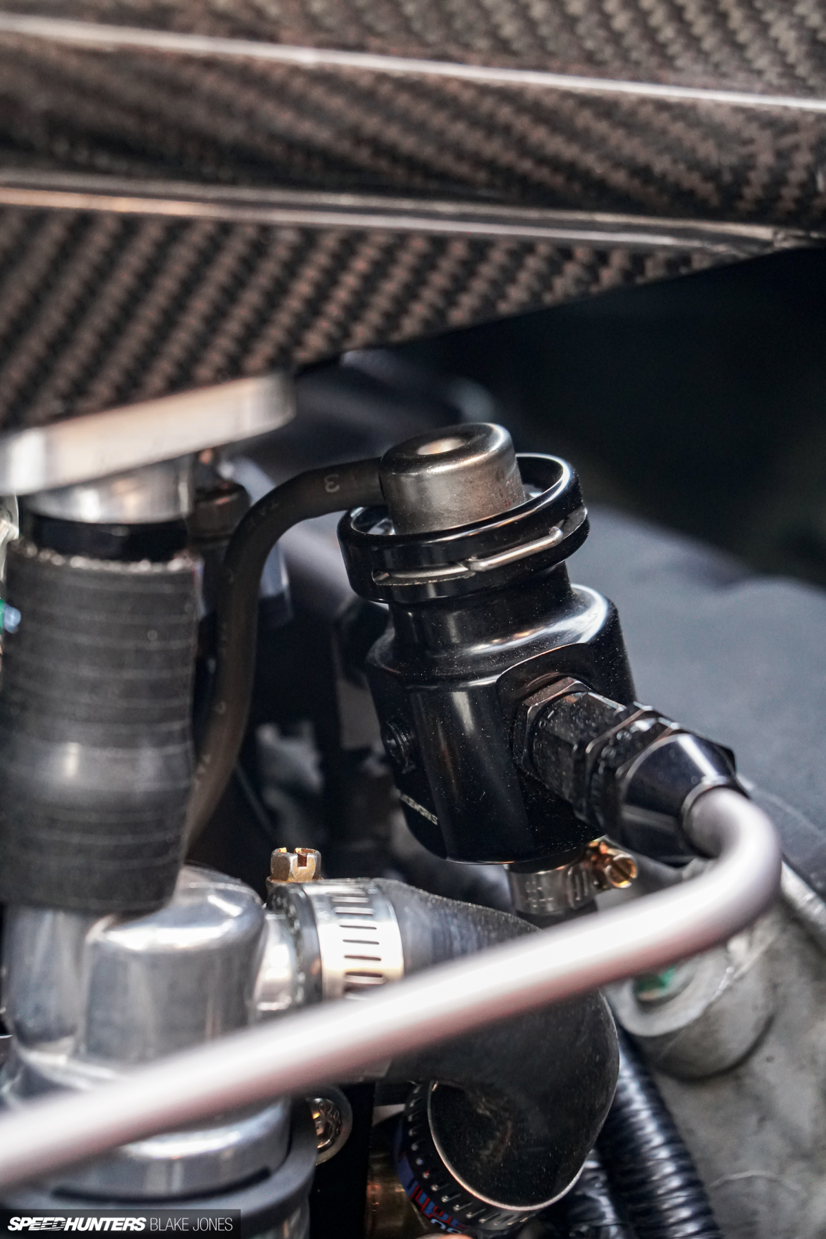
The fuel pressure regulator is a – you guessed it – Bosch 3bar DR2 regulator in a Raceworks billet housing. These ‘pot type’ regulators are affordable and much more reliable than an aftermarket adjustable regulator.
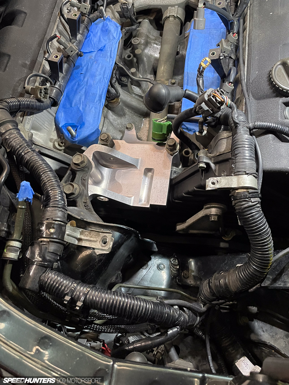
I had intentionally designed the manifold with an offset – a curved runner – to create clearance to the factory alternator and bracket, which encroaches into the motor’s vee. The manifolds, throttles and other hardware cleared fine, but the airbox fouled – due to an unexpected internal detail, I couldn’t get the large box far enough across.
Thankfully, we were able to turn an obstacle into an opportunity. Spoon famously developed and raced an ITB-equipped NSX in period, and had helpfully solved my problem all those years ago. The Spoon lightweight alternator bracket is milled from a huge block of billet, maintaining the required stiffness and factory engine mount point but dropping a handy chunk of weight from the top of the engine.

I try not to fanboy for any brand too much but allow an exception for Spoon Sports – one of my fondest memories of the NSX is Ichishima-san doing a test drive and validation after the Spoon Rigid Collars and steering wheel were installed at Type One back in 2017.
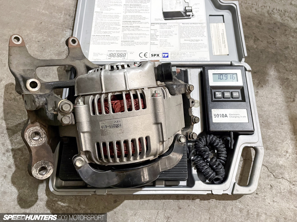
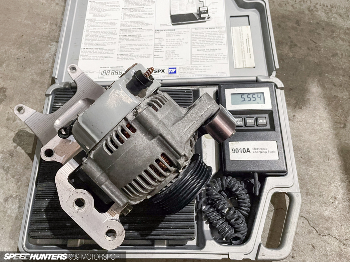
An instant saving of a welcome 5.4kg (11.9lbs) relative to the factory steel bracket.
I caught up with Spoon’s former head of development, Jomoto-san, at WTAC last year, and he gave me a bit of info on these particular parts. They were never released by Spoon for customer cars, but the machinist who produced the parts was permitted to do a small run for some customer requests. Undoubtedly, this part has been through a few different cars before ending up in Project NSX.
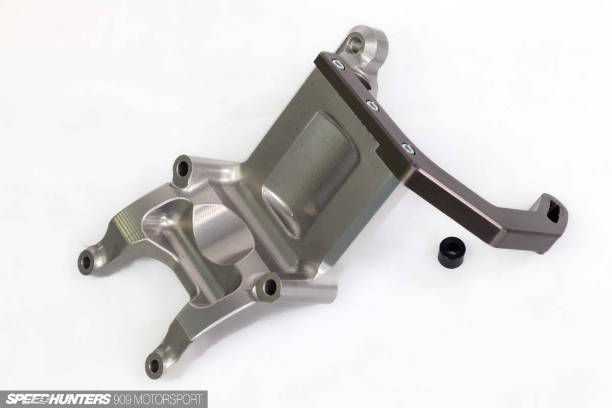
Eric applied a protective anodisation in the titanium colour seen throughout the system, which has elevated the appearance of the already elegant design even further.
Being a race-focused component, the alternator is currently under-driven for road car purposes and we are seeing low battery voltage under certain conditions, so some testing with a smaller pulley will be required.
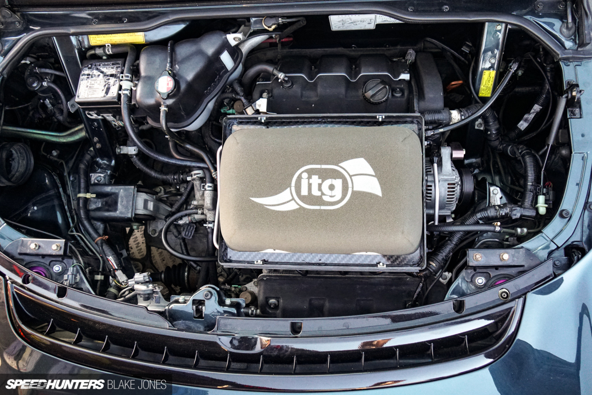
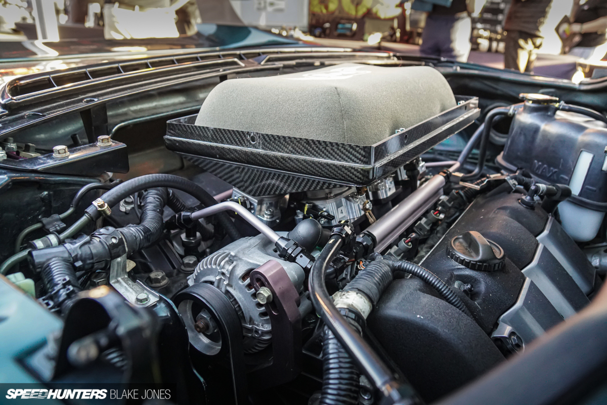
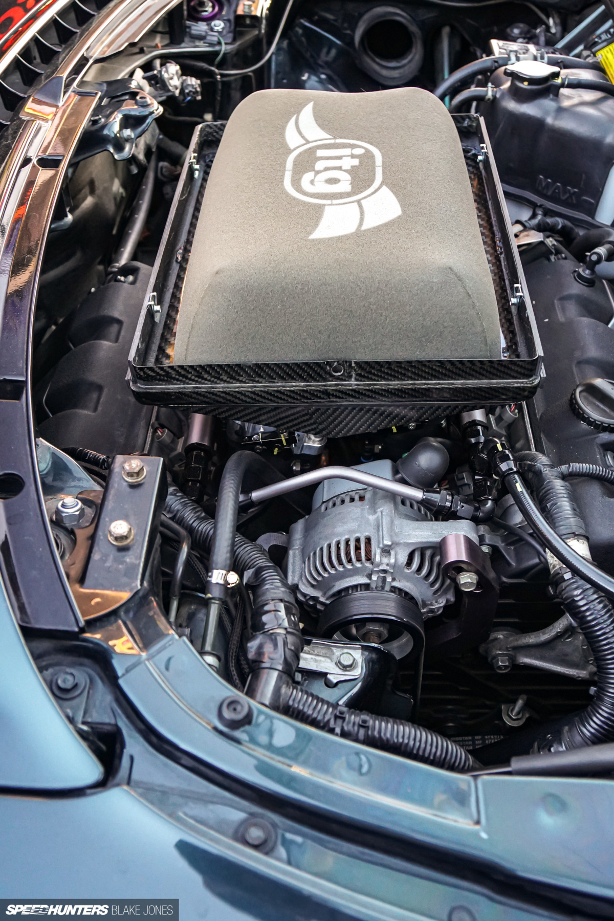
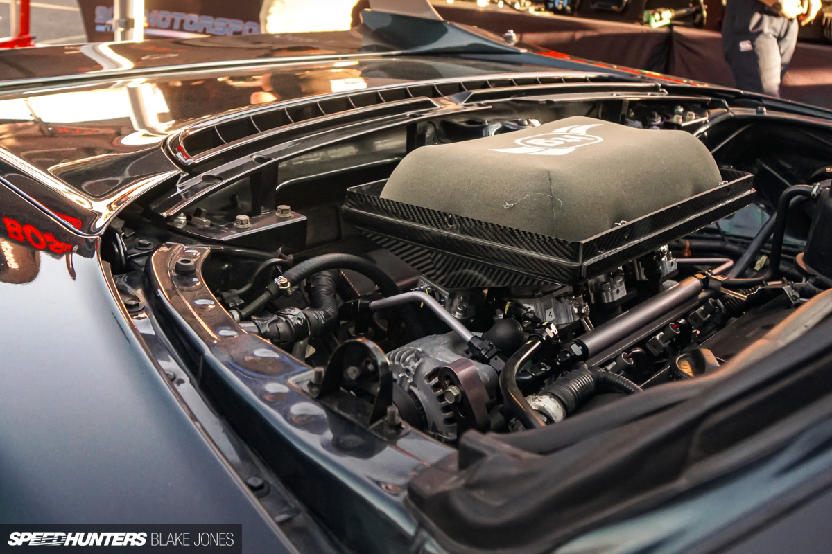
The airbox itself is a semi-custom unit from Reverie in the UK, housing a large ITG foam filter element.
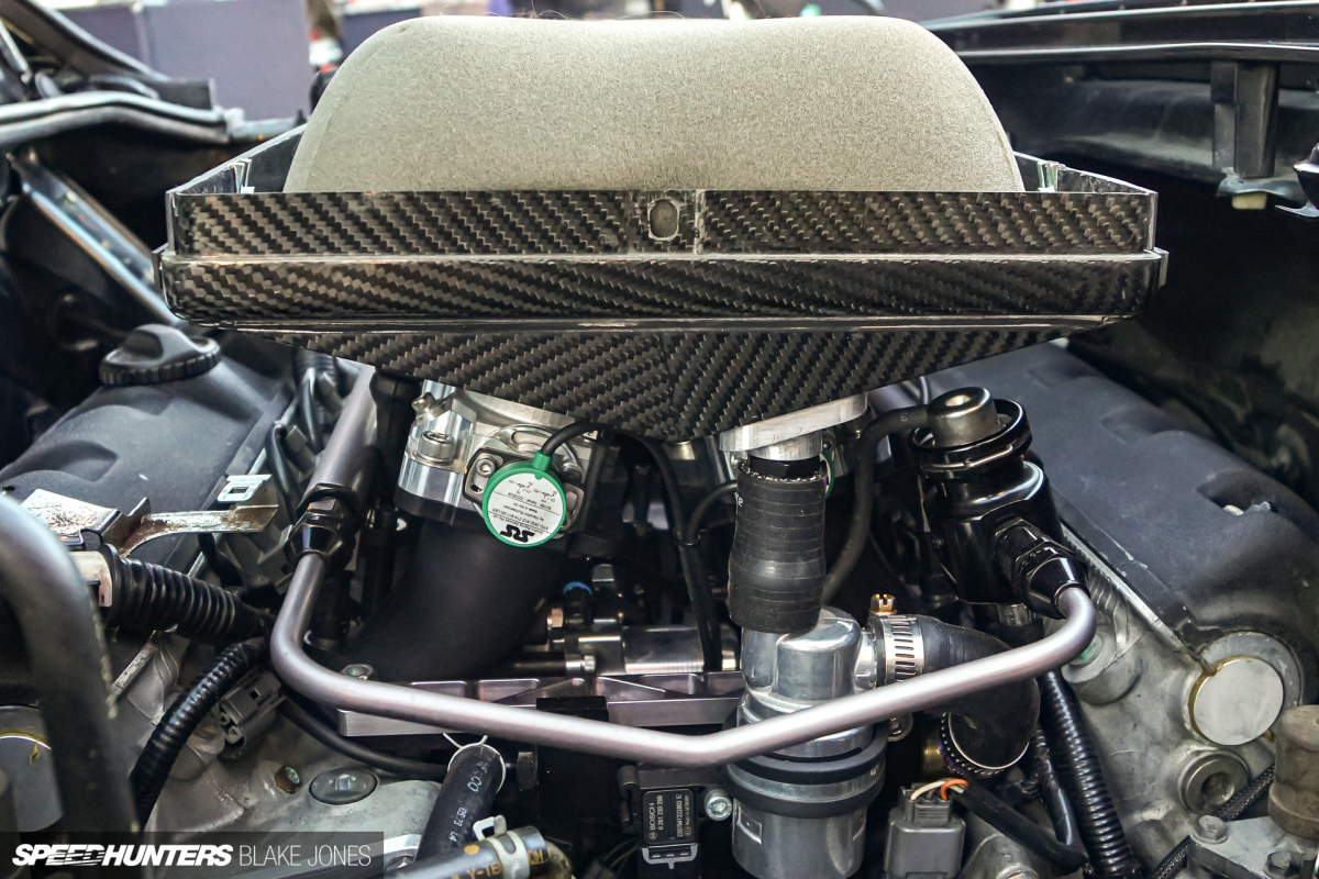
The vee-shaped base had to exactly match the incline of the runners, which it did. This was eye-wateringly expensive but is as light as a feather, looks great and with its inherent resonance properties should sound mega too.
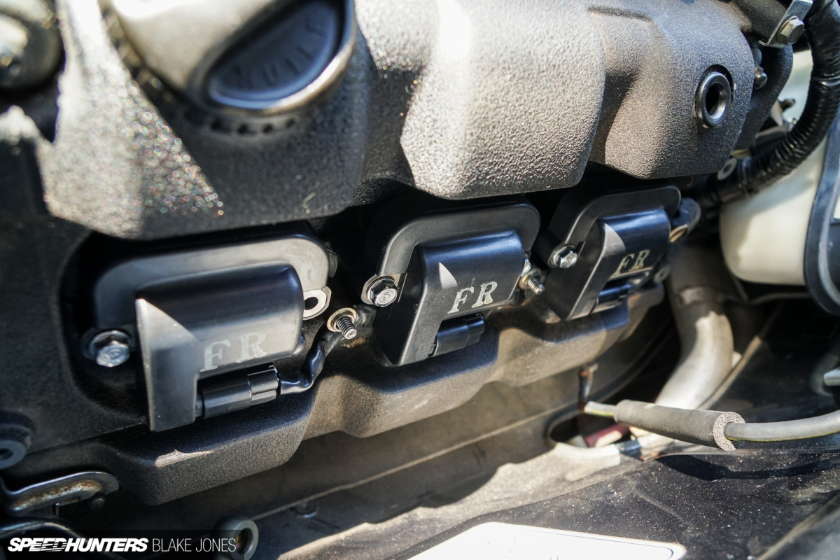
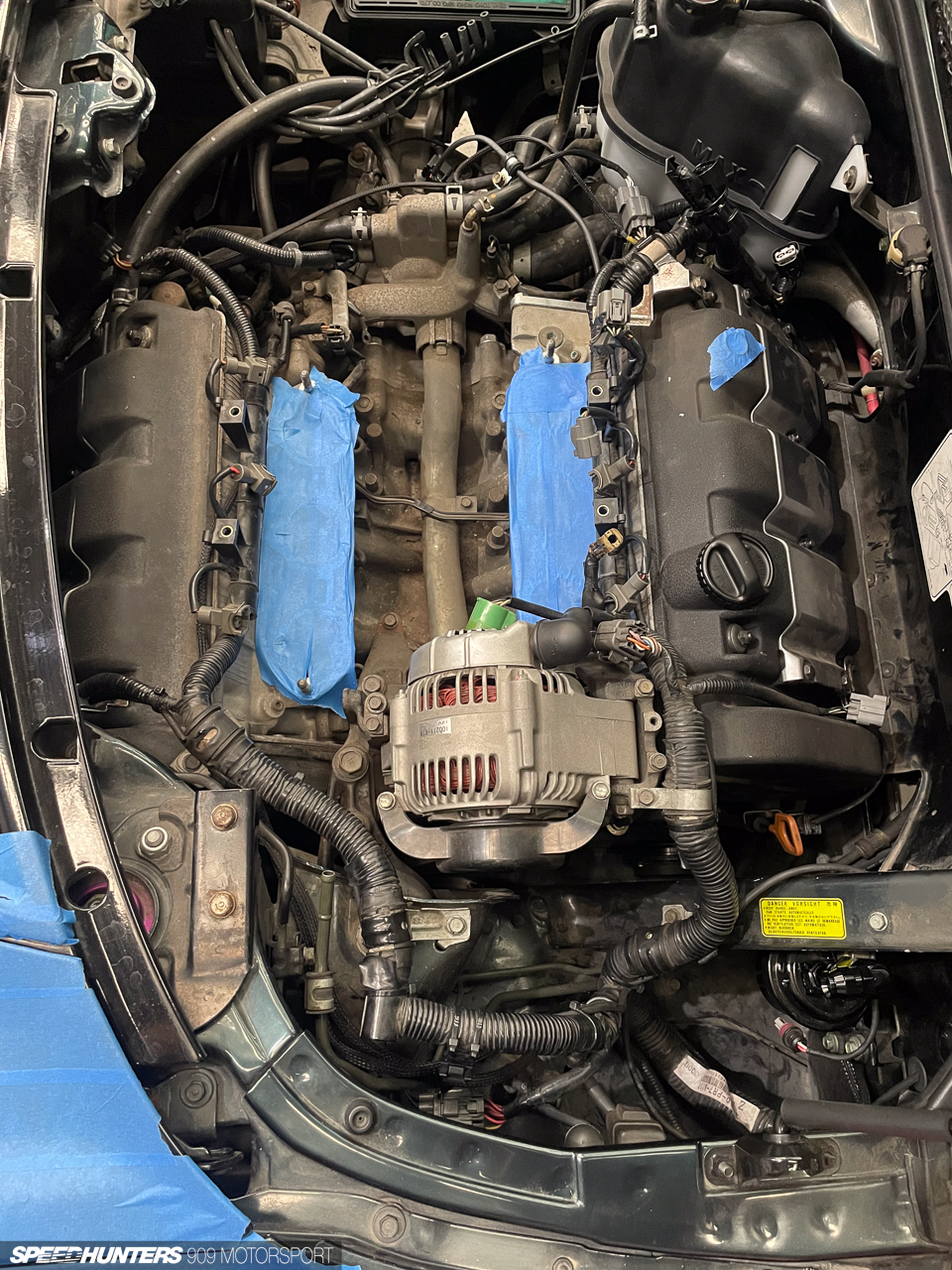
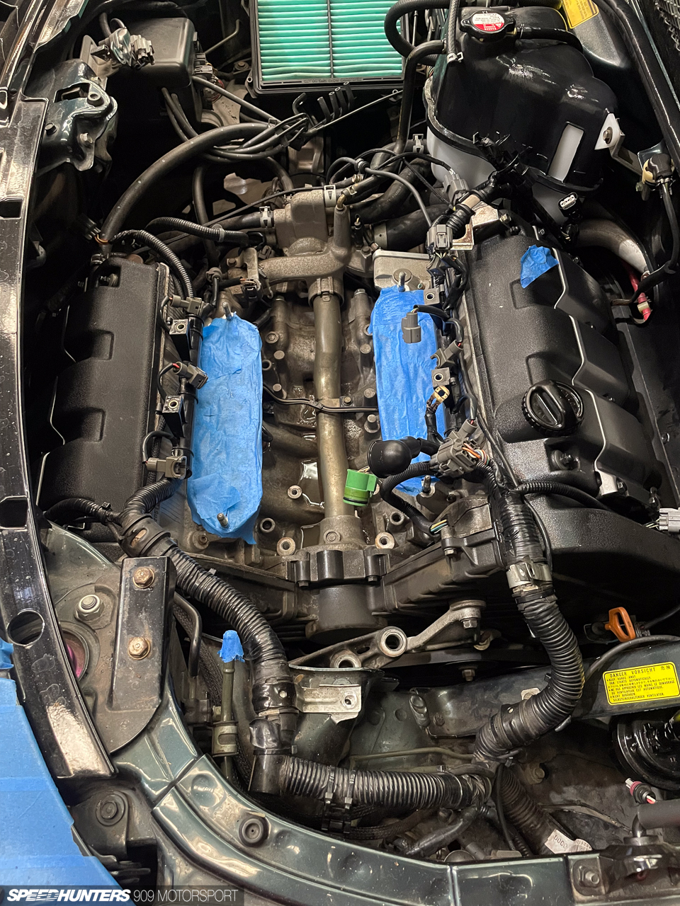
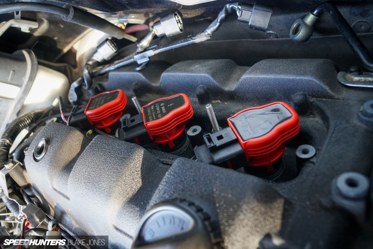
Another small change – swapping out the standard coil packs for something more modern.
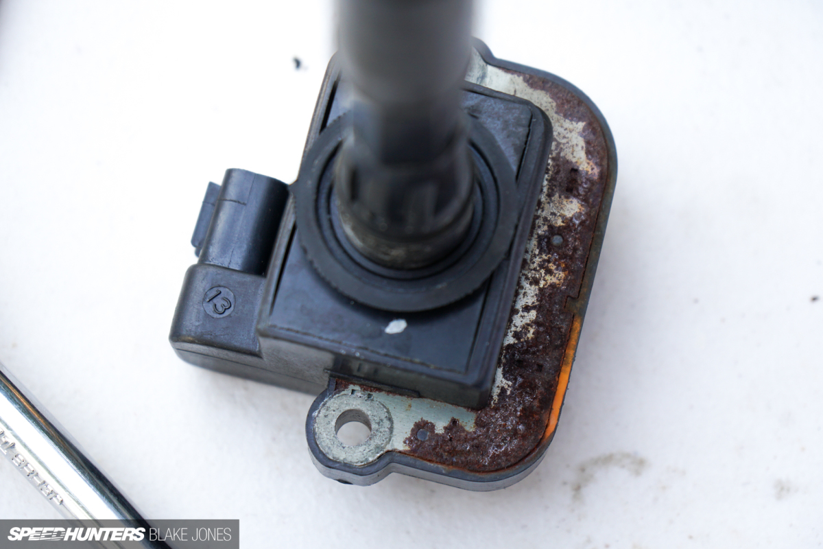
The coils on the NSX’s rear bank are known for deteriorating due to exposure to moisture – exhibit A, your honour.
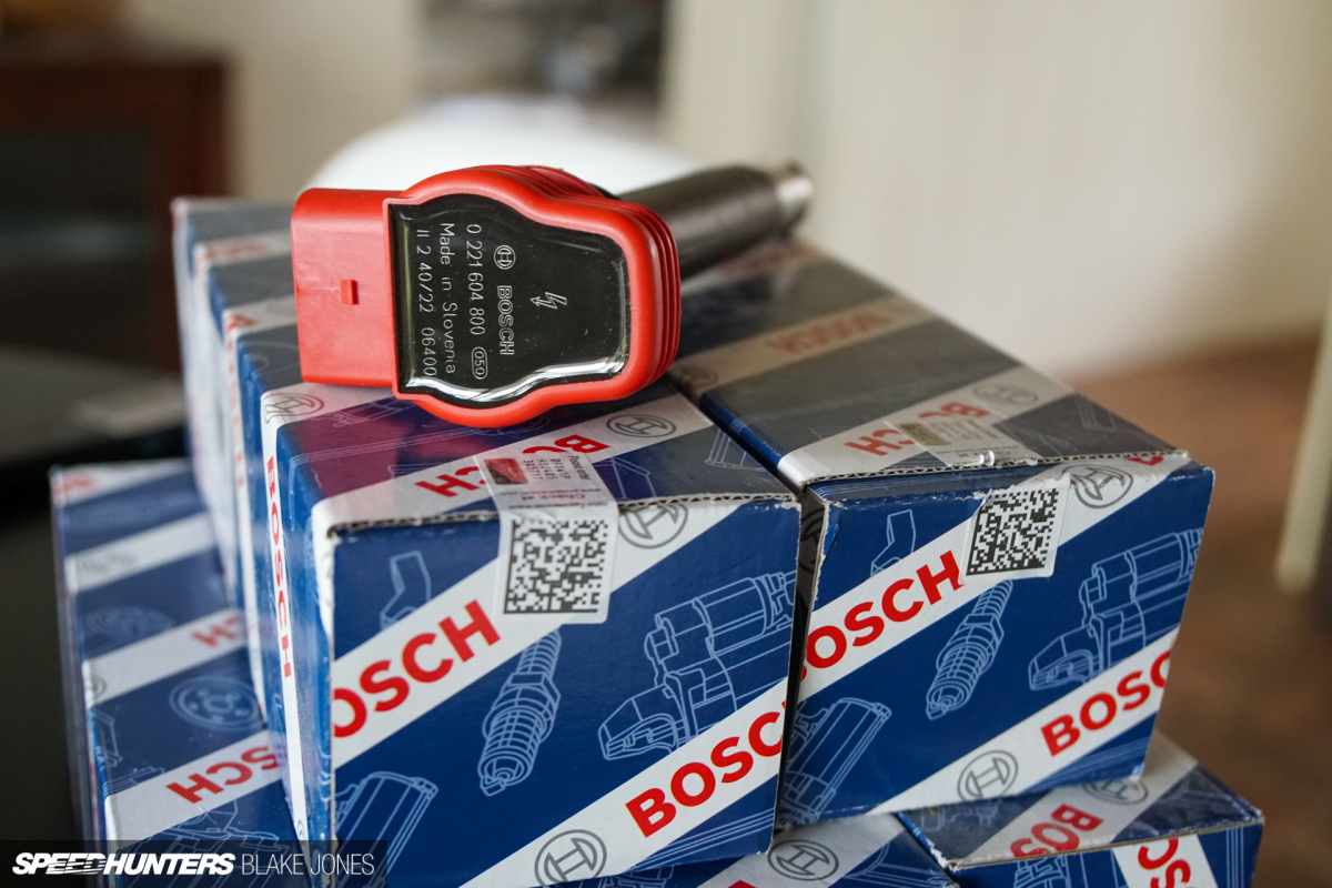
I again reached into the Bosch catalogue for the ‘R8′ ignition coil – a lightweight and affordable OE option that also comes with a fancy red top – so it must be faster.
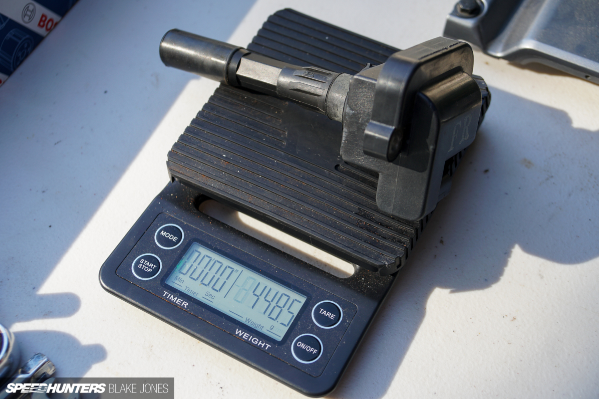
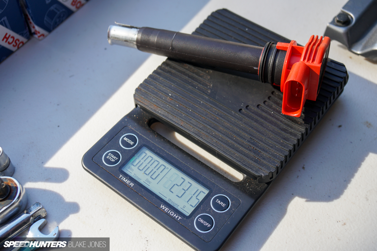
I must admit to being a bit lax with the scales lately, but I did manage to weigh the old and new. Across six cylinders, that’s over 1.3kg (2.8lbs) of coil weight saved.
I’m not expecting a performance benefit here, this engine is still fairly stock without high compression nor boost. But money and weight saved with a future-proof solution, so I’m satisfied.
Assembly To Calibration
So after all that hard work, surely it’s the time to reveal that the car made more power and torque and is the fastest NSX in the Southern Hemisphere? Well, as you may now suspect, it’s not that simple.
We put the car on the dyno with a focus first on getting the car running and driving like stock. There’s still auxiliary work to be done before this new setup can stretch its legs properly – Ash is very particular about what he requires from a vehicle before he chases outright power. However, I did convince him to do a power run that we could compare to baseline – I knew you guys would murder me if we didn’t have one!
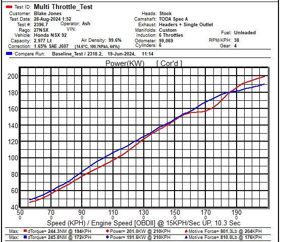
With the short prototype bell-mouths (seen earlier in the story when the intake was mocked up) the headline figure is now 201wkW (269whp) – a 9.4kW (12.8hp) improvement over the baseline set prior (191wkW/256whp). I was expecting a 10 to 15kW (13 to 20hp) increase from the ITBs and there is still significant optimisation to implement – so straight off the bat that is a decent improvement to the top end. However, that is a peak power figure, and the engine has clearly lost both power and torque at other RPM.
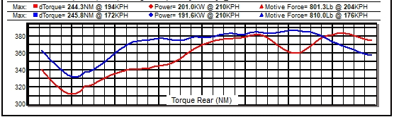
Outside of the enthusiast game, individual throttle bodies are almost always considered to be race car parts, and this result is a good example of why. Race cars are driven in the narrow band of their rev range that makes the most power, and rarely, if ever, need to dip out of that range. Road cars, on the other hand, should be usable over a much wider range, so the driver has access to torque upon request, regardless of what RPM the engine may be cruising at. The factory variable intake was exceptional for that purpose. Its variable geometry (which switched from small to large volume at 4,800rpm) neatly explains the new hole in torque up to 5,000rpm, most pronounced around 4,000rpm. The other dip at 6,800rpm is unusual and will require further investigation when we do some testing with the final intake hardware including trumpets of varying lengths and airbox lid and optimising the VTEC engagement point.
So where does that put us relative to our ‘Stage 2′ target of a nice round 300 crank hp? Some quick maths…
Factory manifold = 191.6rwkW + 27.3kW (measured drivetrain loss) = 218.9kW/293.5 crank hp
Multi-throttles = 201rwkW + 27.3kW = 228.3kW/306.2 crank hp
…I’m satisfied to call that mission success for ‘Stage 2′, which was originally benchmarked against the 987.2 Cayman S on a simplistic power-to-weight basis. We’ve even snuck past the 100hp-per-litre threshold, which is great for an NA engine. However, it’s definitely not job done with some power and torque to be recovered at lower RPM, and perhaps even more to come from the top end with the right supporting modifications. I’m estimating weight reduction to be around 11kg (24lbs), but currently without the exact measurements to confirm.
However the primary win is not measured in tq/hp, but in smiles. Of course, it sounds amazing. An intoxicating crescendo that builds to the VTEC crossover, then absolutely screams to redline. Don’t believe me?
What may particularly impress with those of you who have gone down the ITB path already is that the end result is an NSX with completely uncompromised road manners. At sensible RPM it genuinely drives like a stock car. It starts first bang of the key regardless of the weather. The idle is set at 900rpm! We can chase down the power and torque but right now having a car that is genuinely drivable with a drive-by-wire, vee-configuration ITB setup is something I’m incredibly proud of.
A massive thank you to Ash from 909 Motorsport and Eric from Apex Composites for the effort, skills and motivation they provided throughout this project. Without these guys, I may have by some miracle managed to get ITB system installed on the car but I never would have something that is so robust, beautifully finished and reliable as what we have. Also a special thanks to Rama from RHD engineering, for answering six million questions and getting me the extra bits I needed to get the project across the line. A shoutout also to Tim McLean of TMC Developments for the educated input during the design process.
Blake Jones
Instagram: blaketjones
blake@speedhunters.com
